Posted on

Live RF coverage mapping with ATAK

Highlights

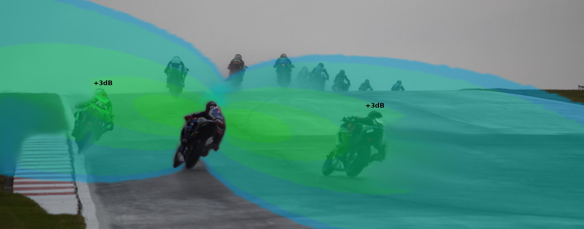
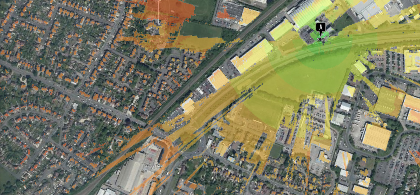
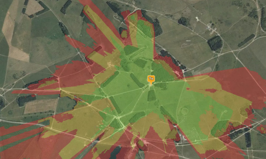
  • Dynamic radio coverage visualisation
  • Vendor agnostic radio integration via ATAK
  • 450 heat-maps delivered without issue
  • Sub-second computation via Cardshark computer

Background

Three years ago we developed a “live” simulation capability using location-aware MANET radios which we described as dynamic radio planning which fused real and planned radio positions. This feature required a third party hardware API with restrictive terms, common in commercial radio, so it exists as a video demo only.

We’ve refreshed and field tested this concept, using modern edge compute and open standards.

ATAK as the common API

Using ATAK as a proprietary API broker, we are now able to do the same via our plugin. The technology agnostic capability can be used with any radio, vehicle or marker on the map and by starting with an open information standard, Cursor-on-Target (CoT), it eliminates the commercial friction with NDAs, proprietary APIs and different vendors.

Open standards unlock low-cost cross-vendor interoperability in a way proprietary standards never can. For example, two vendors can achieve compatibility without knowledge of each other’s products. Better still, compatibility with future products, not yet deployed, can be assured.

Mapping live radios in the SOOTHSAYER ATAK plugin

The field test

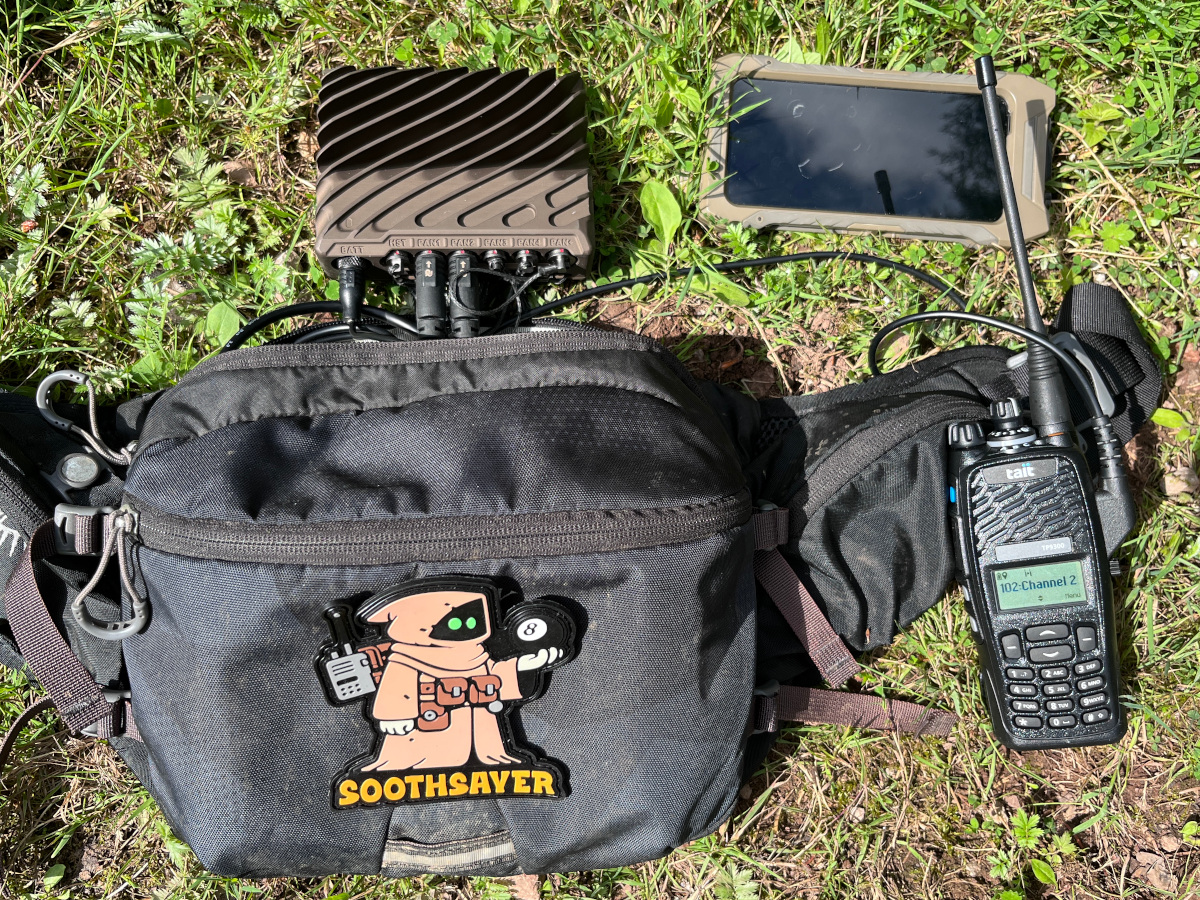
We picked a local Forest to field test this concept using a Cardshark computer which is a rugged Jetson Orin with a 1024 core GPU. We need the GPU to efficiently compute our ‘Multisite‘ network heat maps. The ‘Points‘ links are CPU powered. We’ve worked with Jetsons on previous field tests but under manual control. The automation we’ve added here makes periodic API requests and places the computer under a sustained load.

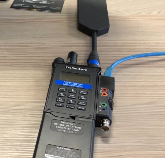
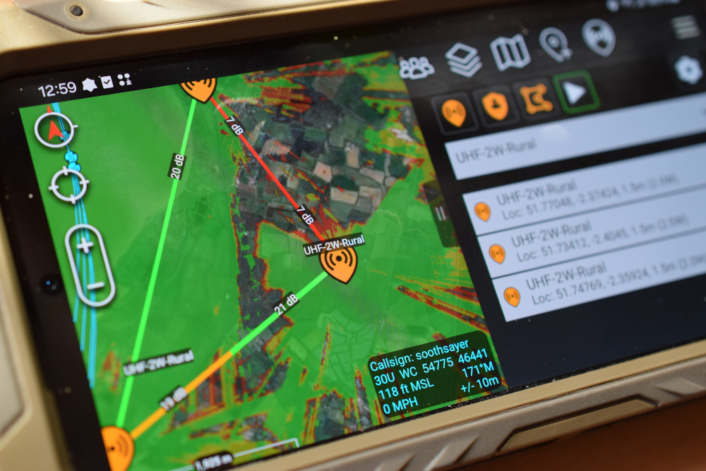
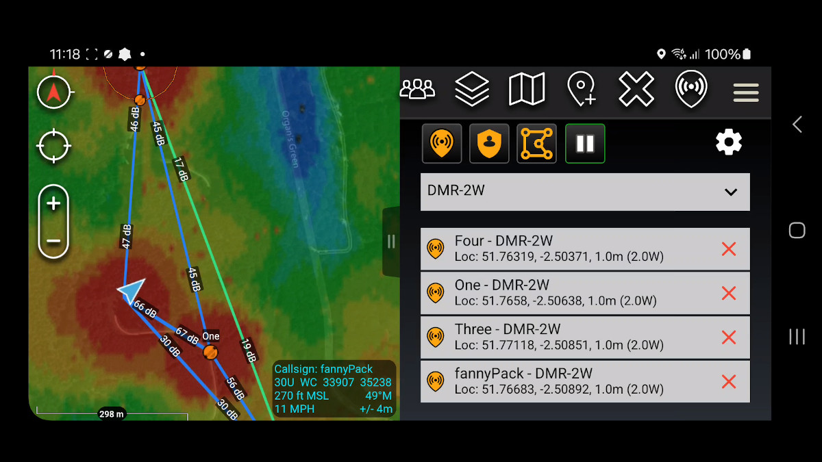
The radio network was a four Tait 9300 DMR portables on a 2W channel, with one donor radio connected via a USB programming cable. GPS locations were fetched using our Tait script which outputs CoT broadcasts to make them appear (and move) upon the map.

The testing went well and produced 450 heat-maps to validate both the concept and the computer. Crucially, our 9Ah battery depleted only by 25% during 2 hours of intensive testing. Our conclusion is that with a reasonable load and refresh rate this edge capability can be scaled to run all day, as we found in Scotland earlier this year.

Live RF coverage mapping with ATAK

Speed test!

Five years ago we asked for the ATAK KML refresh rate to be lowered to enable a “follow me” demo we published and our understanding is it was capped by design at 10s (compared with 1s for Google Earth) due to a concern over excessive bandwidth which was understandable – at the time. A lot has changed in five years of software and radios and now we’re doing the compute locally, this concern is obsolete.

Our GPU engine can model a heatmap in under a second so we bypassed the network KML functionality (which is still a valid way of refreshing heatmaps on ATAK as our Tait plugin does) and implemented our own refresh system, designed for fast moving data. During our speed test, we refreshed the heat-map every 5s which both ATAK and the Cardshark handled comfortably. Logs showed each simulation took under a second with another second for pre/post processing and another for communication. The points requests take 150ms and are called for each radio so four radios would be 600ms, excluding communication.

Issues identified

We identified issues relating to USB tethering which weren’t apparent in the office: The Cardshark does not have WiFi which we employed for previous field tests so this made communication more challenging.

We were able to workaround this for the test with a WiFi hotspot to fool the plugin into thinking it was on a network. As we were using dynamic IP addresses provided by the phone and the Cardshark has no interface, we ex-filtrated the IP information we needed via ATAK which is why there is a IP-address-callsign visible in the video.

The Cardshark is a fanless design which requires airflow to cool it. We deployed it in a bum bag / fanny pack where it unsurprisingly became hot during intensive use but still functioned well. For enduring use, this would need to be mounted externally and the workload throttled accordingly.

Our radio template needed work as only afterwards did we note we did not set the DMR template’s noise floor which defaulted to -133dBm based upon the narrow 12.5KHz bandwidth. This was why there were blue 50dB links visible in the video when in reality the noise floor was likely closer to -113dBm and these links were a more realistic 30dB SNR. This issue did not affect the heatmap which used received power units and we’re satisfied from calibrating with large data sets that the modelling is accurate.

Credits

A special thanks to GoTak LLC who helped us develop and test the live Co-Opt feature in ATAK and Carnegie Robotics for producing the Cardshark and providing timely support.

Links

SOOTHSAYER self hosted server: https://cloudrf.com/soothsayer

Cardshark computer: https://carnegierobotics.com/cardshark

SOOTHSAYER ATAK plugin: https://github.com/Cloud-RF/SOOTHSAYER-ATAK-plugin

Tait ATAK plugin: https://github.com/Cloud-RF/CloudRF-API-clients/tree/master/integrations/Tait

Fanny pack: https://www.osprey.com/gb/osprey-seral-7-s23?size=One+Size&colour=Black

Posted on

Planning for noise

The trouble with radio planning software

Radio planning software has a patchy reputation. Regardless of cost, the criticism, especially from novice users, is generally that results “do not match the real world”. The accuracy of modelling software can be improved with training, better data, tuned clutter etc but if you do not plan for the local spectrum noise, it will be inaccurate.

The reason modelling does not match the real world, is the real world is noisy, and noise is everything in digital communications. Spectrum noise will limit your network’s coverage and equipment’s capabilities. A radio that should work miles can be reduced to working several feet only when the noise floor is high enough.

Anyone expecting simulation software to produce an accurate result without offering an accurate noise figure will be forever disappointed as software cannot predict what the noise floor is in a given location at a given moment – you need hardware for that…

Spectrum sensing radios

Modern software defined radios are capable of sensing the noise figure for the local environment. This allows operators, and cognitive radios, to make better choices for bands, power levels and wave-forms as narrow wave-forms perform better in noise than wider alternatives due to channel noise theory where noise increases with bandwidth.

For example, you can have a radio capable of 100Mb/s but it won’t deliver that speed at long range, at ground level, as it requires a generous signal-to-noise margin to function. This is why a speed demo is always at close range.

When spectrum data is exposed via an API, like in the Trellisware family of radios, it provides a rich source of spectrum intelligence which can be used for radio network management, and dynamic RF planning with third party applications. When we integrated this radio API last year, we were focused on acquiring radio locations, not spectrum noise. At the time we could only consider a universal noise floor value in our software so the same noise value was applied for all radios which was vulnerable to error as radios in a network will report different noise values.

Interference: a growing issue

The single biggest communications problem we hear about, from across market sectors, is interference, either deliberate, accidental, or just ambient like in a city. The number of RF devices active in the spectrum, especially ISM and cellular bands, is increasing and in markets which were relatively “quiet”, such as agriculture. Some have always been problematic, such as motorsport, where the noise floor increases significantly on race days.

Spectrum management is a huge problem which won’t be fixed with management consultants or artificial intelligence. Regulators can, and are, restructuring spectrum for dynamic use but to use this finite resource efficiently, hardware and software vendors need to publish APIs and competing vendors need to be incentivised to work to common information standards.

As noise increases, the delta between low-noise RF planning results and real world results has the potential to grow. There’s anecdotal evidence that some private 5G network operators are experiencing so much urban noise they’ve given up on RF planning altogether, and have opted to take their chances using a wet finger and local knowledge. Skipping RF planning is a managed risk when a company has experienced staff (or they get paid for failure), but it does not scale and is a significant risk when working in a new area and/or with inexperienced staff.

A solution: The noise API

To address this challenge, we’ve developed a noise API to eliminate human error, and guesswork for noise floor values which has undermined the reputation of “low-noise” radio planning software.

Manual entry can now be substituted for a feed of recent, or live, spectrum intelligence to enable faster and more accurate network planning. Combined with our real-time GPU modelling, the API can model coverage for moving vehicles, with real noise figures.

There are two new API requests in v3.9 of our API; /noise/create; for adding noise, and /noise/get; for sampling noise. The planning radius is used as a search area so you can upload 1 or thousands of measurements, private to your account. The planning API will reference the data, if requested, and if recent (24 hours) local noise is available for the requested frequency, it will sample it and compensate for the proximity to the transmitter(s).

When no noise is available within the search radius, an appropriate thermal noise floor will be used based on the channel bandwidth and the Johnson-Nyquist formula. The capability can be used by our create APIs (Area, Path, Points, Multisite) by substituting the noise figure in the request eg. “-99” for the trigger word “database”.

{
  "site": "2sites",
  "network": "MULTISITE",
  "transmitters": [
    {
      "lat": 52.886259202681785,
      "lon": -0.08311549136814698,
      "alt": 2,
      "frq": 460,
      "txw": 2,
      "bwi": 1,
      "nf": "database",
      "ant": 0,
      "antenna": {
        "txg": 2.15,
        "txl": 0,
        "ant": 39,
        "azi": 0,
        "tlt": 0,
        "hbw": 1,
        "vbw": 1,
        "fbr": 2.15,
        "pol": "v"
      }
    },
    {
      "lat": 52.879223835785716,
      "lon": -0.06069882048039804,
      "alt": 2,
      "frq": 460,
      "txw": 2,
      "bwi": 1,
      "nf": "database",
      "ant": 0,
      "antenna": {
        "txg": 2.15,
        "txl": 0,
        "ant": 39,
        "azi": 0,
        "tlt": 0,
        "hbw": 1,
        "vbw": 1,
        "fbr": 2.15,
        "pol": "v"
      }
    }
  ],
  "receiver": {
    "alt": 2,
    "rxg": 2,
    "rxs": 10
  },
  "model": {
    "pm": 11,
    "pe": 2,
    "ked": 1,
    "rel": 80
  },
  "environment": {
    "clm": 0,
    "cll": 2,
    "clt": "SILVER.clt"
  },
  "output": {
    "units": "m",
    "col": "SILVER.dB",
    "out": 4,
    "res": 4,
    "rad": 3
  }
}: 

In the example JSON request above, two adjacent UHF sites are in a single GPU accelerated multisite request. The sites both have a noise floor (nf) key with a value of “database”. Noise will be sampled separately for each site.

Demo 1: Motorsport radio network on race day

The local noise floor jumps ups significantly on race day compared with the rest of the time making planning tricky.

Demo 2: Importing survey data to model the “real” coverage across a county

By importing a spreadsheet of results into the API, we can generate results sensitive to each location.

A look forward to cognitive networks

Autonomous cognitive radio networks require lots of data to make decisions.
Currently, they can use empirical measurements of values such as noise to inform channel selection and power limits at a single node.
What they cannot do is hypothesise what the network might look like without actually reconfiguring. To do that requires a fast and mature RF planning API, integrated with live network data. Only then can you begin to ask the expansive questions like, which locations/antennas/channels are best for my network given the current noise or the really interesting future noise whereby the state now is known but the state in the future is anticipated.

As our GPU multisite API can model dozens of sites in a second, the future could be closer than you think…

References

API reference: https://cloudrf.com/documentation/developer/swagger-ui/

Hosted noise client: https://cloud-rf.github.io/CloudRF-API-clients/integrations/noise/noise_client.html

GPU multisite racetrack demo: https://cloud-rf.github.io/CloudRF-API-clients/slippy-maps/leaflet-multisite.html

Posted on

GPU propagation engine

5G cell

Our fast GPU engine is perfect for modelling wireless coverage

We have developed the next generation of fast radio simulation engines for urban modelling with NVIDIA CUDA technology and Graphics Processing Units (GPUs).

The engine was made to meet demand across many sectors, especially FWA, 5G and CBRS for speed and accuracy.

As well as fast viewsheds, it enables a new automated best-site-analysis capability, which will accelerate site selection and improve efficiency whilst keeping a human in the loop. As we can do clutter attenuation, it’s suitable for VHF and LPWAN also.

Designed for 5G

5G networks are much denser than legacy standards due to the limited range of mmWave signals, necessary for high bandwidth data. The same limitation means these signals are very sensitive to obstructions, and Line of Sight (LOS) coverage is essential for performance.

With 1 metre accuracy and support for LiDAR, 3D clutter and custom clutter profiles, you can model rural and urban areas with high precision.

We can do Trees too

Unlike simplistic viewshed GPU tools designed for speed, we can model actual tree attenuation for beyond line of sight sub-GHz signals such as LPWAN and VHF. Trees can be configured as clutter profiles, along with shrubs, swamps, urban areas and 18 classes of Land cover and custom clutter.

Area coverage

The simplest mode is a fast “2.5D” viewshed (with a path loss model) which creates a point-to-multipoint heatmap around a given site using LiDAR data. Ours has better Physics than some of the “line of sight” eye candy on the market and doesn’t have trouble with Sub-GHz frequencies which are harder to model accurately.

This is up to 50 times faster than our multi-threaded CPU engine, SLEIPNIR.

GPU demo January 2022

In this mode we can do diffraction and material attenuation with our custom clutter classes.

Best site analysis

Best Site Analysis (BSA) is a monte-carlo analysis technique across a wide area of interest to identify the best locations for a transmitter. This can be done quickly with a new /bsa API call. The output will identify optimal sites, and just as important, inefficient sites.

This feature is powerful for IoT gateway placement, 5G deployments and ad-hoc networking where the best site might presently be determined by a map study based on contours as opposed to a LiDAR model.

Best Site Analysis on ATAK

High speed

Our GPU engine is up to 50 times faster through the API than the current (CPU) engine SLEIPNIRTM

By harnessing the power of high performance graphics cards, we are able to complete high resolution LiDAR plots in near real time, negating the need for a “go” button, or even a progress bar. This speed enables API integration with vehicles and robots which will need to model wireless propagation quickly to make better decisions, especially when they’re off the grid. It was designed around consumer grade cards like the GeForce series but supports enterprise Tesla grade cards due to our card agnostic design.

Economical

Our implementation is efficient by design. We want speed to model wireless coverage but not if it requires kilowatts of power. During testing we worked with older GeForce consumer cards and were able to model millions of points in several milliseconds with less than 50W of power. Or in other words, the same power as flicking a light bulb on and off.

Any fool can buy large cards and waste electricity, but we’re proud to have a solution which is fast and economical. This also means it can be run on a laptop as it’s available now as our SOOTHSAYER product.

Open API

The GPU engine is an “engine” parameter in our /area API so you can use it from any interface (or your own custom interface) by setting the engine option in the request body. The OpenAPI 3.0 compliant API returns JSON which contains a PNG image so for existing API integrations using our PNG layers there will be no code changes required to enable it.

Self-hosted GPU server

Instead of buying milk every month you can buy the cow. We also sell SOOTHSAYER which is a self-hosted server with our GPU engine onboard. It supports NVidia GPU cards from Maxwell architecture onwards and most enterprise Hypervisors like ESXi and Proxmox. You get to use your existing LiDAR data too, so you’re not buying it twice.

To see how easy it is to setup a GPU card with SOOTHSAYER we’ve made a video:

SOOTHSAYER GPU setup

Accessible

Using GPU cards to model Physics, including EM propagation, is an established concept dating back 20 years, despite businessmen claiming otherwise. What is novel here, is making this exciting technology accessible to users priced out of premium tools.

Staying true to CloudRF’s accessible and affordable principles, we’ve included it in our service as an optional processing engine.

CloudRF is a member of the NVIDIA inception program