Web Interface Overview
The 3D web interface is the primary user interface for CloudRF. This interface is compatible with desktops, laptops, tablets and even mobile phones.
The interface supports Android, Linux, Mac/OSX and Windows and works best with Google Chrome.
MINIMUM HARDWARE: 4GB of memory, dual core CPU
RECOMMENDED HARDWARE: 8GB of memory, quad core CPU, 1GB GPU
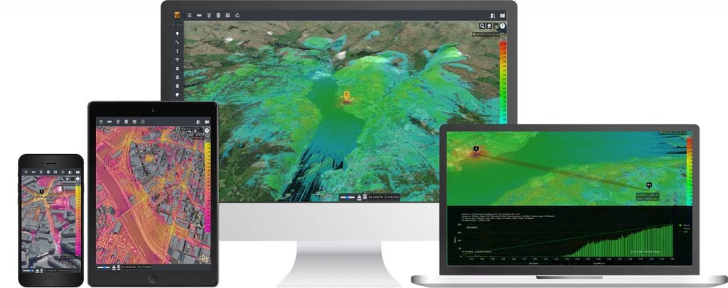
To access the CloudRF 3D Interface:
Click on the Web Interface button on the Home Page.
Interface elements

Hot Keys / Keyboard Shortcuts
There are a number of hot keys / keyboard shortcuts which are enabled in the interface which can allow you to manipulate your view/settings without moving your mouse.
You can use the following keyboard shortcuts:
Home- Reset your view to your current Tx marker.Page Up- Zoom out.Page Down- Zoom in.Left Arrow- Pan view left.Up Arrow- Pan view up.Right Arrow- Pan view right.Down Arrow- Pan view down.Control + Left Arrow- Move Tx marker left.Control + Up Arrow- Move Tx marker up.Control + Right Arrow- Move Tx marker right.Control + Down Arrow- Move Tx marker down.Control + Space- Run a calculation.
UI Mode
The CloudRF UI supports users of different radio knowledge.
You can quick toggle between the two modes by clicking on the mode name which you are currently using.
Engineer Mode
Engineer mode will be indicated by “Engineer” in the UI Mode portion in the top left of the window.
In engineer mode you will have full access to all tools and input fields to fully customise your requests.
This mode is typically used by advanced users, or those who wish to fine-tune calculations.
Operator Mode
Operator mode will be indicated by “Operator” in the UI Mode portion in the top left of the window.
Operator mode is designed to provide the minimum required fields to allow a user to execute calculations, whilst avoiding overwhelming with fields which might not be fully understood. Therefore, in operator mode you will notice that many of the tools and input fields are removed. If you wish to use these then you should use a different mode.
This mode is typically used by beginner or novice users, or those who don’t need to be able to fine-tune settings.
The following settings are used when making use of operator mode.
The general purpose model is used as the propagation model (See model section for more details).
Deygout 94 is used as the diffraction model (See model section for more details).
A DTM elevation is used with landcover and 3D buildings (See environment section for more details).
Various values are calculated which would otherwise be manually input:
Noise floor and receiver sensitivity are inferred from the bandwidth value which is used.
The maximum radius is calculated based upon the maximum theoretical radius that could be achieved based upon your settings.
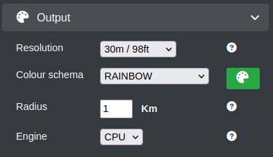
The resolution of the output is calculated based upon the maximum megapixel output which can be produced by your subscription plan and combining it with your specified radius. A larger radius will result in a reduced resolution output.
Transmitter Marker
The Transmitter Marker (Tx) indicates your Antenna Location.

To update your antenna location settings:
On the map, click on the desired location.
The transmitter marker will move to your clicked location.
The location settings under the input menu will be updated respectively.
Click on the transmitter marker to view the location parameters of the Transmitter - Latitude and Longitude.

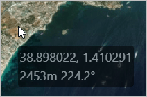
When you have a layer, the information box next to the cursor will display the current co-ordinates, signal strength, distance and angle from the site.
Templates
Templates allows you to quickly apply settings from a saved/custom or system-defined configuration.

Templates are useful in a shared account where an Engineer might prepare the template(s) and a sales person might use them to qualify customers.
Custom Templates
To manage your custom templates:
Configure the Input Menu as per your requirement.
Click on the Save
 button.
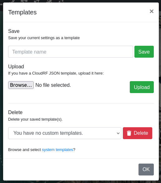
The Manage Your Templates dialog box will appear.
Saving a Custom Template
To save a custom template:
After configuration in the Input Menu, click on the Save
 button.
In the Manage Your Templates dialog box.
In the Template Name field, enter the desired name of your custom template.
You can give a user-friendly name, for example: “Radio X”.
Click on Save button.
The created Template will be displayed under My Templates drop-down. All custom templates will be prefixed with the words “Custom”.
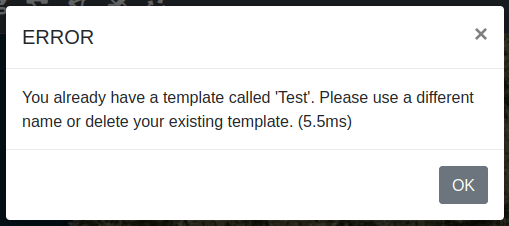
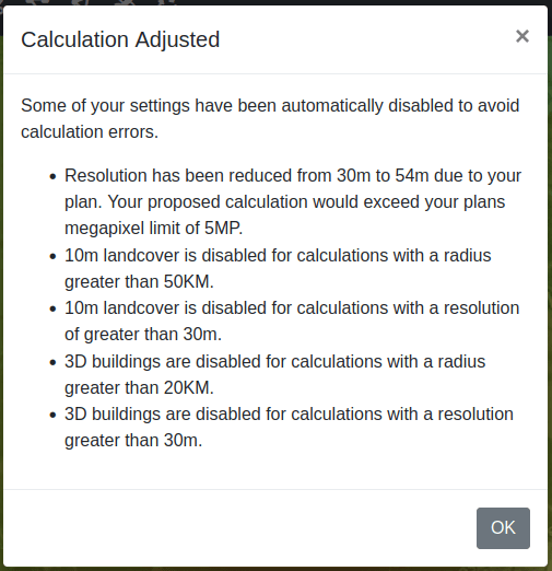
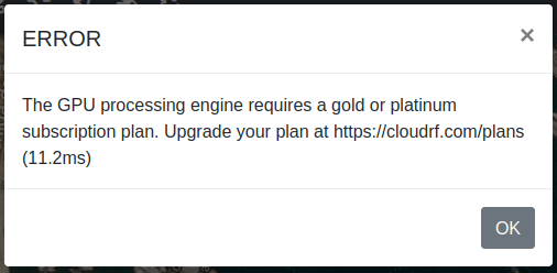
If your settings have any issues when you attempt to create a tempalte then you will be notified via a modal window.
An example of a bad template upload is below.
Uploading a Custom Template
You can upload templates directly into the system. This is useful if you would like to create and share your own templates.
To upload a custom template:
Click on the “Browse…” button to search through your local filesystem to find the JSON template which you wish to upload.
Click on the “Upload” button.
The template will be uploaded and validated. If your template has all of the required fields in the correct formats then your template will be made available to use in your user account. If your uploaded template has any problems then you will be notified via a modal window.
An example of a bad template upload is below.

Deleting a Custom Template
To delete a custom template:
Click on the Template save
 button.
In the Templates dialog box.
In the Delete field, select the Template Name that you wish to delete.
Click on Delete button.
The deleted Template will be removed from the My Templates drop-down.
System Templates
System Templates provide a list of pre-built templates, built from product data sheets.
To manage your system templates there are 2 methods:
Click on the “Templates” button
 in the manager in the “Account Information” modal.
Click on “system templates” in the “Templates” modal.
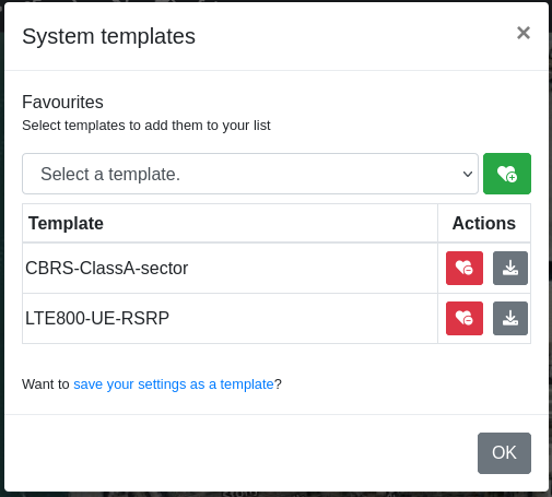
Favouriting System Templates
To add a system template to the templates dropdown you can find the template you wish to favourite from the select list, then click the favourite button  .
.
The chosen template will then be shown in the list below where you will have the option to either remove it or download the system template as a JSON file.

When you have favourited a system template it will be populated into the My Templates dropdown and will be prefixed with the words “System”.
Unfavouriting System Templates
To unfavourite a system template click on the “Unfavourite” button  .
.
This will remove it from the list of templates at the bottom of the system-template manager, but also from the My Templates dropdown.
Downloading System Templates
To download the content of a system template click on the “Download” button  .
.
This will download directly to your browser the raw content of the template in a JSON file. You may edit this in any text editor. A reference for the values is linked in the header of each file.
Download Templates
You can download the raw content of a template directly to your browser by clicking on the download button to the right of the dropdown.

This will download the template as a JSON text file. This will contain all of the settings related to applying that template.
You can download both custom and system templates in this way. You may edit this in any text editor. A reference for the values is linked in the header of each file.
Template privacy and copyright
A template file is potentially sensitive as it can describe equipment configurations and performance. User templates are stored in a user’s private folder with a random cryptographic hash to prevent file guessing attacks. The copyright for a created template belongs to the customer and (JSON file) sharing is actively encouraged.
Output Console
The output console provides the useful feedback related to the settings, errors, API inputs and API outputs as you use the CloudRF tool.
The Effective Radiated Power (ERP) and the computed resolution (in mega-pixels) will be printed in this console as you adjust the settings so that you can keep an eye on the same.
As an area calculation processes, you will see periodic updates in the console from the SLEIPNIR propagation engine.
When you submit a calculation for processing, all the API parameters will be displayed here. If you are a developer, you can directly copy paste this to use it in your code.
To do so:
Click on the Run button for execution, the Site name (Network name) field will be displayed in the Output Console.
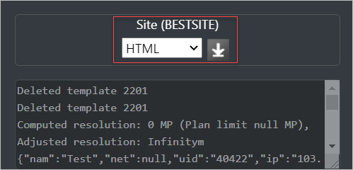
Select the file format in which you wish to download the configuration settings file.
Click on Download
 icon.
icon.
System Version
In the top right corner of the interface indicates the current version of the API and UI which you are using. The discrete green / amber / red light to the left denotes connectivity to the backend processing service / API. Green is good, amber is connected but the API has been under a sustained load for more than a minute and red is API unavailable.

You can click on either of the API or the UI which will open up a modal window in the interface which will give you a full changelog of what has changed in the version you are using.
 Documentation
To refer to the 3D Interface Documentation:
Click on the Documentation
 button located on the top right of the interface.
 Account Information
You can view information about your account by clicking on the Account Information  icon located on the top right of the interface.
When you click on this a modal window will be opened which will contain various information.
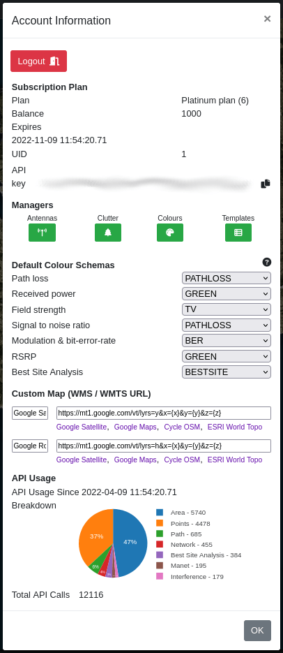
Logout is used to log you out from the system.
Operator / Engineer Mode is used to toggle between operator and engineer mode. See UI Mode for more details.
Subscription Plan contains information about your current subscription details.
Managers are buttons to other tools to allow you to customise your system settings.
Default Colour Schemas allows you to specify which colour schemas are selected by default for each of the available measured units.
Custom Map lets you define either WMS or WMTS URLs which can be used in the UI to set your own custom map service.
API Usage gives a breakdown of your API usage over the period of your subscription.
Logout
You can logout from the interface by clicking on the logout button at the top of the “Account Information” modal.

Subscription Plan
Details about your current subscription plan are listed in the “Account Information” modal. Such information includes:
Your plan name.
Your account balance.
The expiry date of your current subscription.
Your UID.
Your API key, with a quick copy button.
Managers
CloudRF by default may not have the required settings or customisations which you require, and so we include a number of different managers to allow you to build elements yourself.
 Manage My Antennas allows you to import your own antenna patterns. Please consult the antenna management reference for further details.
 Manage Clutter Profiles allows you to define the height and attenuation of environments. Please consult the clutter profile management reference for further details.
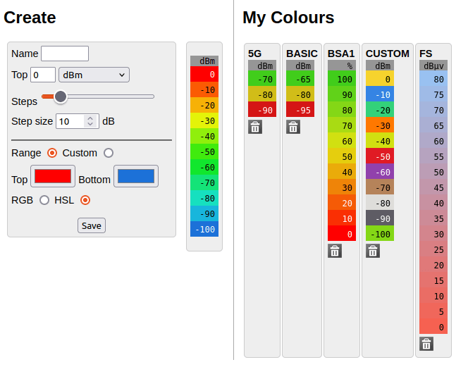
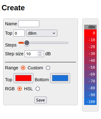
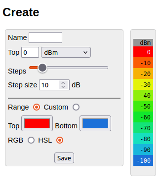
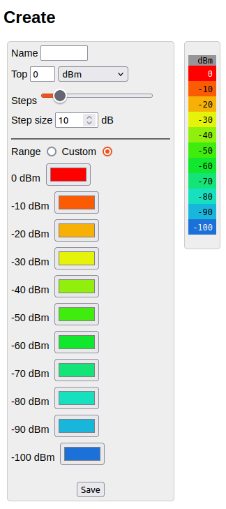
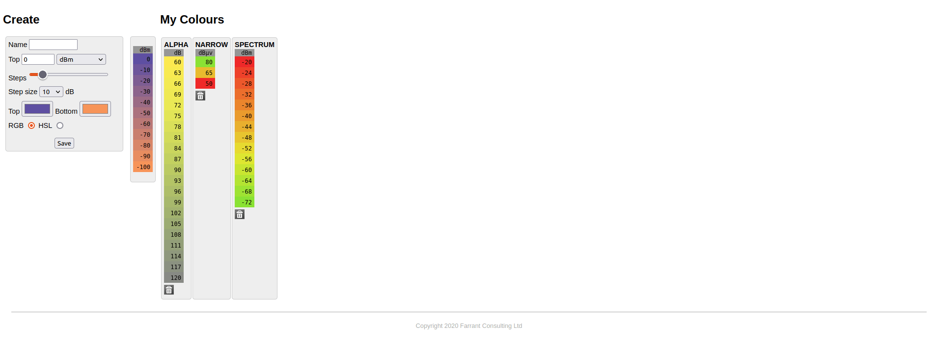
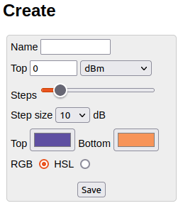
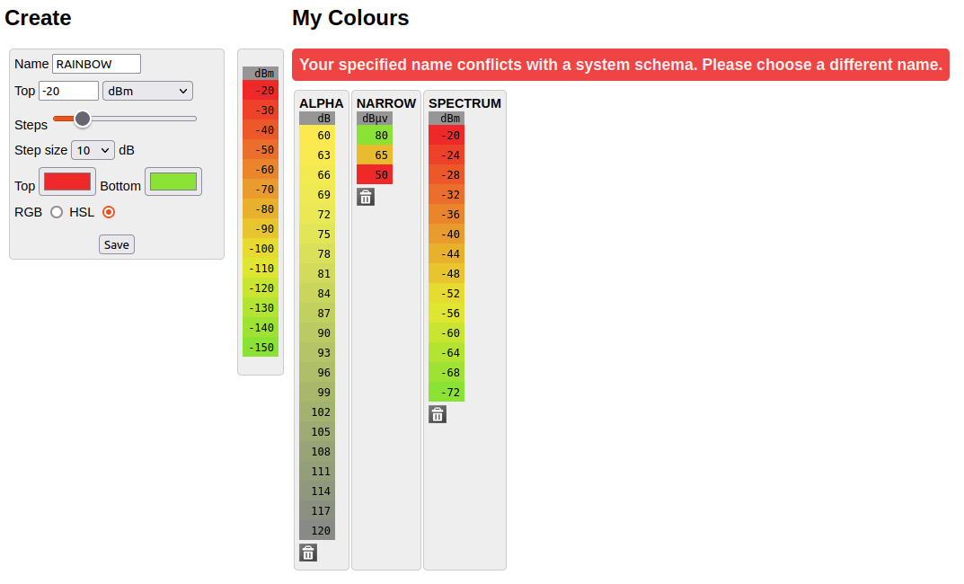
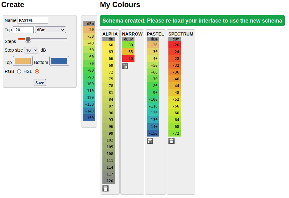
 Manage My Colours allows you to build your own colour schemas. Please consult the colour management reference for further details.
 Manage System Templates allows you to manage your favourite system templates which can be quickly selected from the My Templates dropdown. Please consult the templates reference for further details.
Default Colour Schemas
With CloudRF we support a number of different measured units. As such there are limitations to using some measured units with some colour schemas. The utility in this section allows you to easily select a default colour schema for a number of different measured units:
Path loss
Received power
Field strength
Signal-to-noise ratio
Modulation and bit-error-rate
Reference Signal Received Power (RSRP)
Best site analysis
The schema which you choose here will be the default when you switch your measure unit in the “Mobile / Receiver” menu.
Custom Map
The Custom Map URLs let you define your own map tile servers which can then be used in the interface and selected on the imagery icon. This is useful if the default map layers provided do not meet your own particular needs or requirements.
API Usage
API usage will give you a breakdown of your usage since your subscription was created. This includes a chart and full breakdown of the number of each individual API requests.
Mobile Operation
The CloudRF 3D Interface can be easily accessed on your mobile phone.
The following UI will be displayed on your mobile phone, with a collapsed menu:
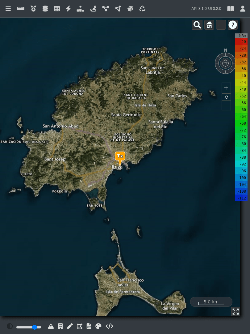
3D Interface Elements - Mobile View
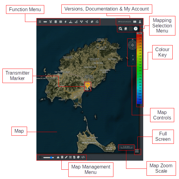
Expand/Collapse
The Expand/Collapse  button of the Function Menu lets you expand or collapse the Side Menu consisting of Templates, Input Menu and Output Console.



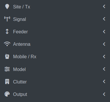
 icon beside them. To know the details regarding a field, you can click on the Help icon of the respective field.
 Site / Tx
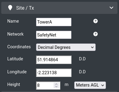
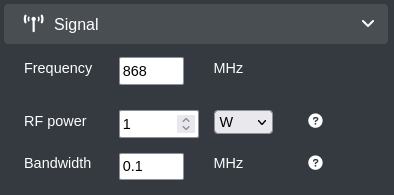
 Signal
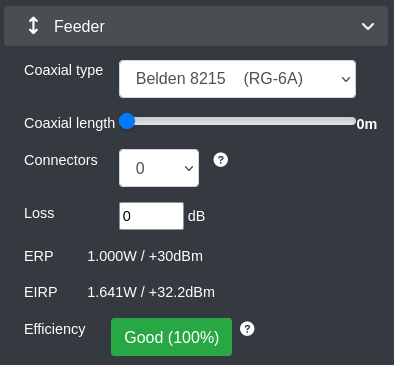
 Feeder
 Antenna
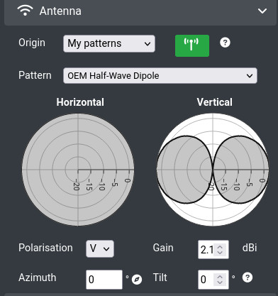

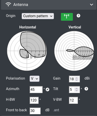
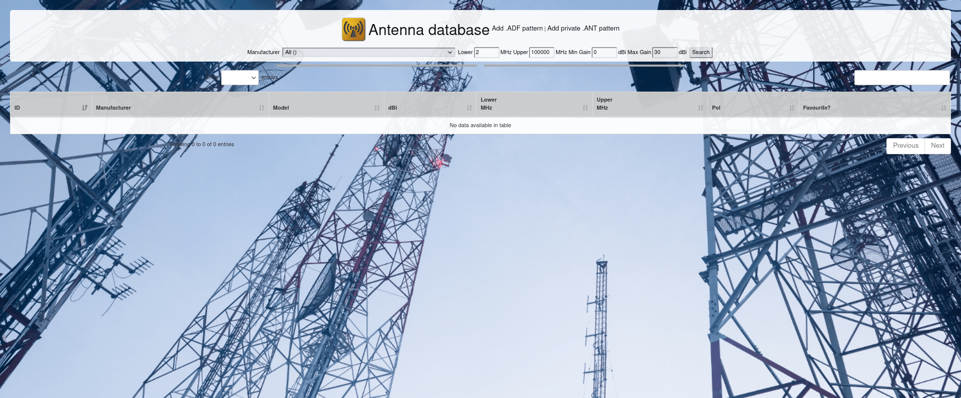
 icon of the pattern.
 indicating that the pattern has been short-listed. It will appear in your antennas list after re-loading the user interface.
 Mobile / Rx
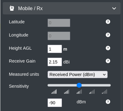
 icon on the Function Menu.
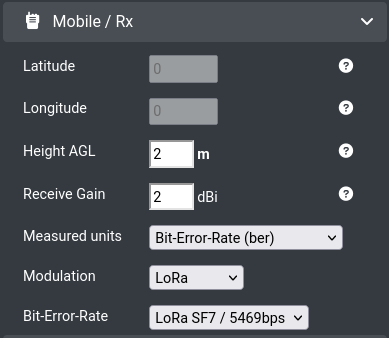
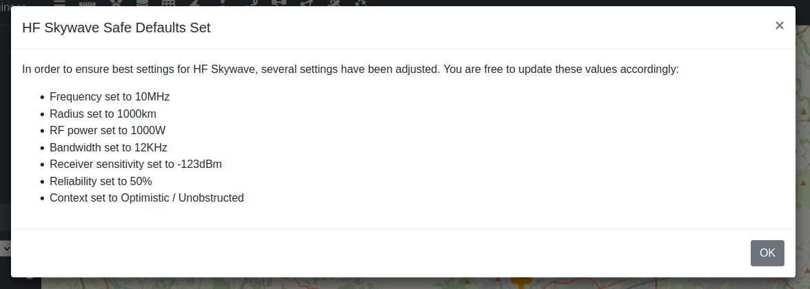
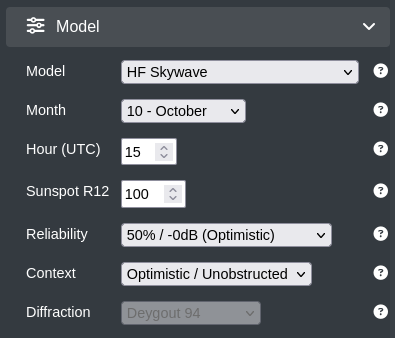
 Model
Model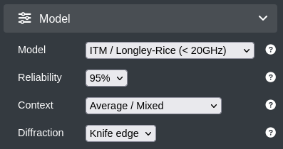
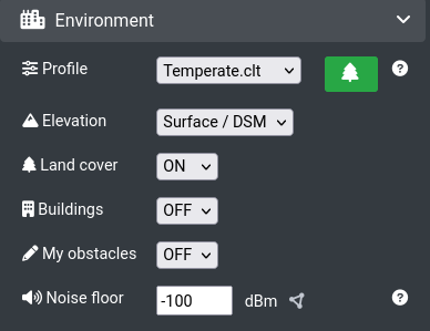
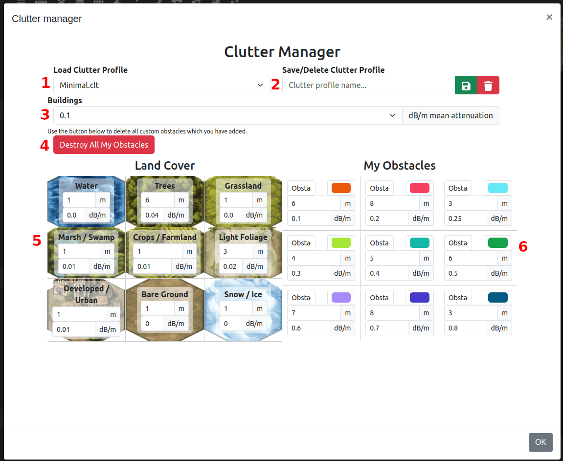
 Environment

 Output
 Run
Run