A motorsport customer invited us to a track day to observe a peculiar RF problem…
High resolution ‘dashcam’ video feeds have become standard in motorsport with multiple cameras present on vehicles and drivers. Unlike a consumer dashcam, these real-time video feeds use TV broadcasting radio links to relay a signal from the vehicle to the video processing facility via track-side receivers. The problem is Motorbikes with video feeds were experiencing RF difficulty on bends despite being close to high gain receiving antennas. This issue was investigated with the CloudRF API which revealed the following findings:
- Lean angle has a direct impact on signal quality
- Adjacent riders will attenuate signals
- A bike at full tilt will experience antenna polarisation loss
- Mast heights must be wavelength x (distance/4) to compensate for dynamic losses
- Low masts, like tight boots, are terrible!
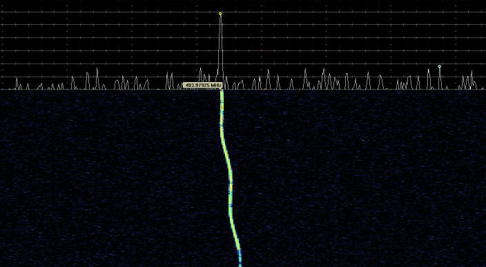
Doppler shift
The system must contend with several challenges; firstly the doppler effect caused by a shifting emitter. This effect is negligible at slower speeds but can cause reception issues as the vehicle increases speed and the frequency appears off tune.
A superbike moving at 100mph would result in as much as a 5% shift in frequency which depending on the location of the receiver could be an increase or decrease of 1MHz. The effect can be modelled and managed with frequency tracking receivers designed to overcome this high speed issue.
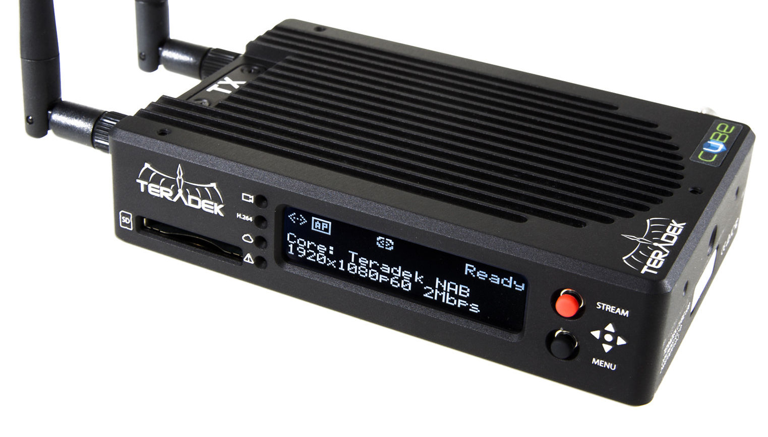
Lightweight RF links
Weight is critical in maintaining a competitive edge so the RF links employed are low power emitters, using the vehicle’s
native electrics. Licensing restrictions also limit the maximum allowed power output.
The standard used in this case is
ISDB-T which is an MPEG-4 H-264 high definition video stream which at full rate employs QAM-64 modulation.
The H-264 quality High Definition (HD) video feeds people are accustomed to require a high signal-to-noise ratio of at least 20dB which is achieved by careful deployment of track-side high gain antennas and dedicated broadcasting spectrum at 2.3GHz.
The system uses 7MHz of bandwidth (broken down into sub-carriers) which has an absolute noise floor of -105dBm.
Adding the necessary 20dB SNR gives -85dBm which with the addition of 10dB of environmental (7dB) and receiver (3dB) noise gives a target threshold of
-75dBm.
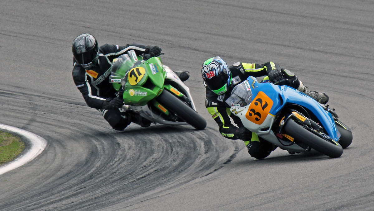
The antenna on the motorbike is a shark fin, vertically polarised design mounted on the tail of the bike behind the rider.
For the purposes of this investigation the antenna has been modeled with 1dBi gain and and an ERP of 18dBm / 65mW,
equivalent to just under a consumer WiFi router.
The video broadcast unit is concealed nearby within the bike’s tail with minimal cabling between the antenna for tidiness and maximum efficiency.
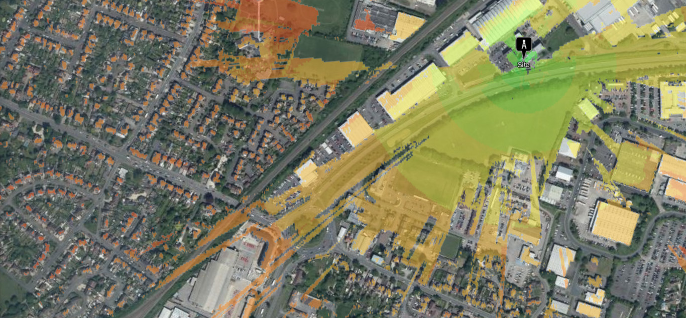
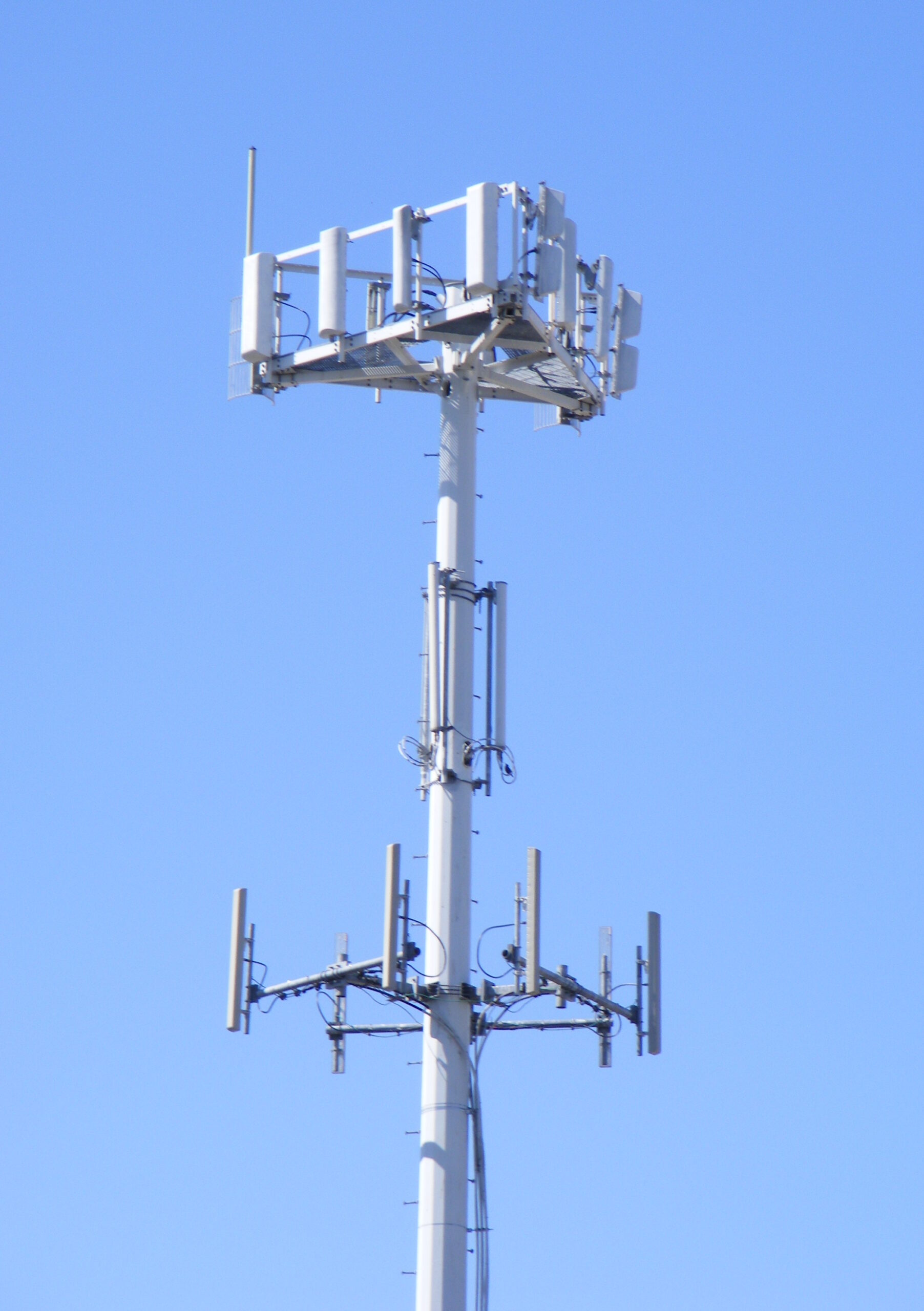
The track-side antennas would be directional antennas with at least 10dBi of forward gain. These would be positioned at key
points on the race track for maximum benefit. The siting of these antennas is where CloudRF is used to test options.
Bends
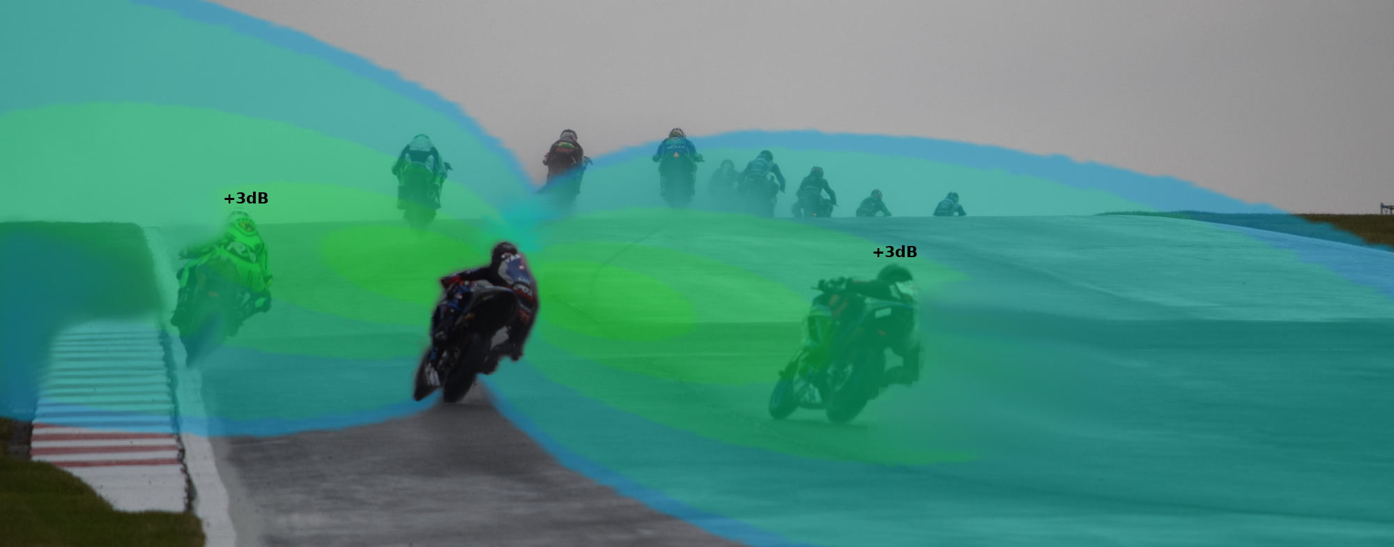
Using GPS data from races, it was found that there could easily be 8 motorbikes in a tight group on a bend.
As the bikes all take the bend, several changes occur which all impair RF propagation, resulting in disruption to the smooth HD feed:
1. Rider attenuation
A significant change to consider is the increase in environmental attenuation caused by the crowd of riders.
At 2.3GHz the human body will absorb 3dB of RF power. Assuming there are 3 bikes between the rider and the receiver this could
be a substantial +9dB of attenuation – comparable to a brick wall (7dB) at this wavelength.

2. Antenna tilt
As bikes lean on a bend so do their vertically polarised antennas. As an antenna deviates from its optimal polarity (vertical)
to horizontal it loses power up to 3dB at full tilt (90 degrees). If a bike is at half tilt, polarisation loss will cost the
RF link 1.5dB.
3. Antenna height
Coupled with tilt, the height of the antenna above the earth will reduce from ~100cm to as little as ~50cm. This will reduce its
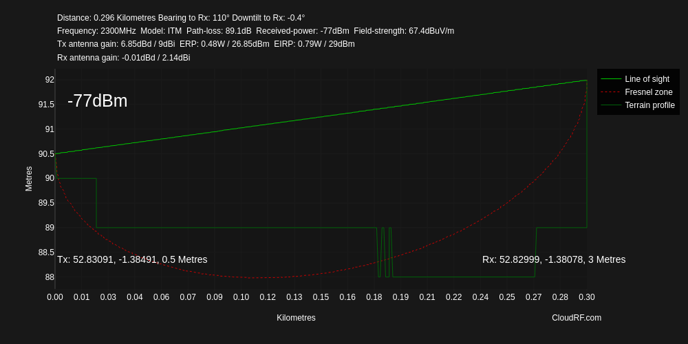
effectiveness as more of the key fresnel zone will be attenuated by the earth. Using a fresnel zone calculator the fresnel
zone radius for a 2.3GHz link over 300m is 3 metres. Elevating the track side antennas on masts is one way to overcome
this issue but when one end of the link is so near the earth the (tower) elevation must be much higher than the fresnel radius if it is to clear the earth completely as these profile images demonstrate.
Modelling using the Irregular terrain model which considers fresnel attenuation shows substantial loss caused by minor reductions in the (bike) antenna height. As you can see in the path profile below, the curved fresnel zone clips the earth which introduces attenuation.
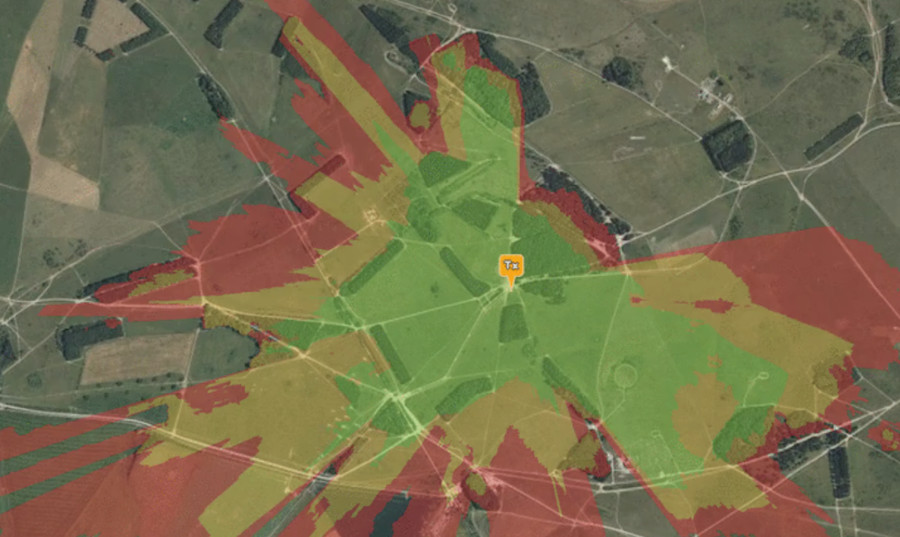
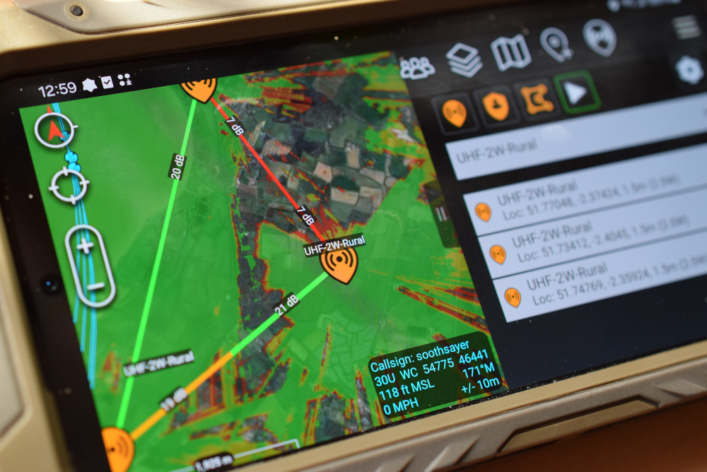
Modelling the problem with the CloudRF API
The customer wondered if the issue might be identified through Monte-Carlo simulations whereby random inputs, in this case bikes, were placed on the track and the coverage mapped for comparison. This type of simulation is possible through the coverage API with custom client scripts and can help identify where to site receive antennas around a given track.
After much deliberation it was realised that the benefit of area modelling would be limited in contrast to focusing on the impact of a bend on a
single bike which could be adjusted for different lean angles and simulated crowds.
For this study the Path Profile (PtP) API was used to focus on a short 300m straight line path between a bike and a mast, with variation to the inputs.
The bike’s height was adjusted to simulate lean based upon a starting height of 100cm (Superbike tail height average) down to a minimum of 50cm when at full tilt.
The impact of adjacent riders was simulated by adjusting the receiver gain downwards, in this case by 9dB to simulate 3 other riders.
The significance of receiver height was demonstrated by adjusting the mast to clear the fresnel zone at this distance.
Results
The following data was generated using the ITM model with transmission heights ranging from 1m (Bike is upright) to 50cm (full lean). The ITM model considers the effect of the obstruction of the fresnel zone which is the cone of power around the path of a signal.
Measurements are based upon a mast 300m away, on flat earth, with a 9dBi sectorial panel antenna. The zone grows deeper as it travels so mast height must consider this as well as line of sight clearance.
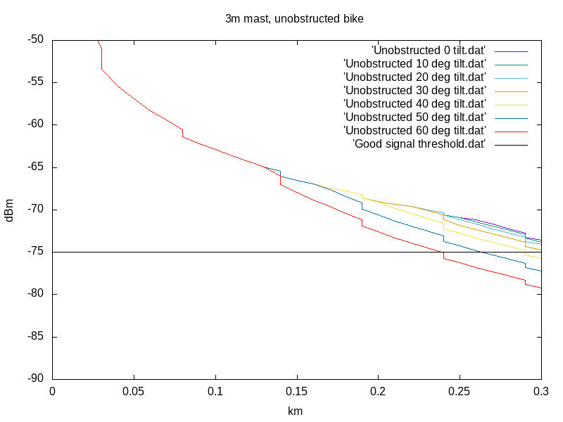
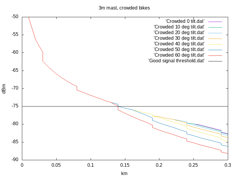
3m mast
A 3m mast is higher than most vehicles and ground clutter but only for line of sight. At 300m the fresnel zone is 3.12m so this mast height is only high enough up to about 250m before power is lost as the fresnel zone is attenuated by the earth.
Results show that without obstructions 3m is borderline as bikes lean and as soon as a bike is obstructed by another it falls below the target threshold, regardless of lean angle.
3 metre mast, unobstructed | 3 metre mast, obstructed
|
| 
|
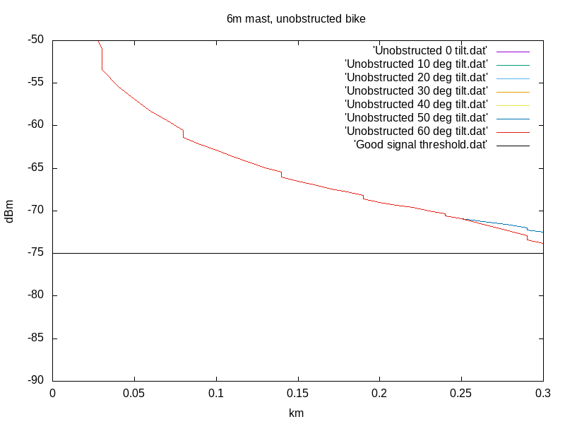
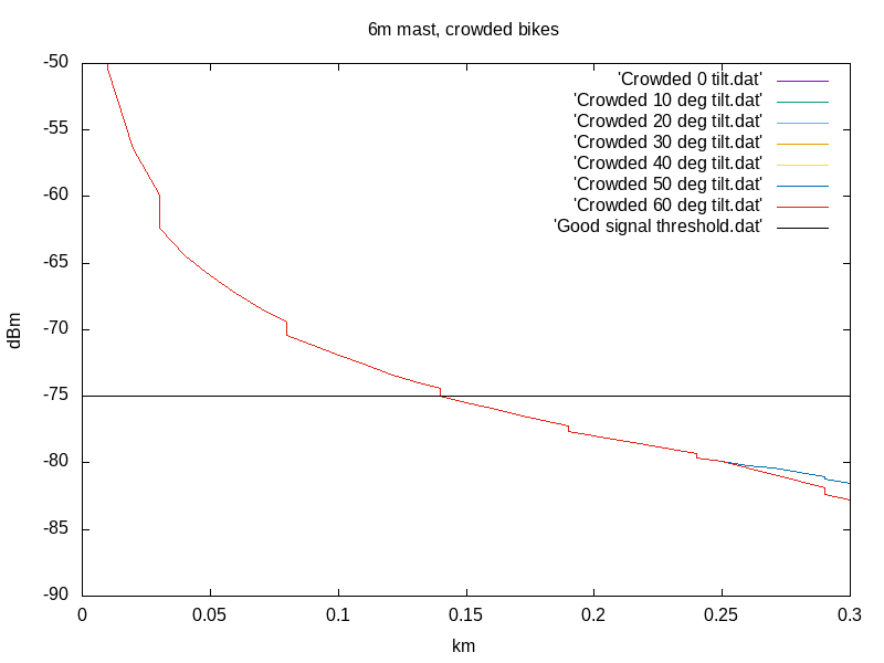
6m mast
A 6m mast is a major improvement. Being well clear of the fresnel zone makes it able to handle a full 60 degree lean at 300m.
Results show that without obstructions 6m is good for all scenarios and if a bike is obstructed by others it only falls below the target threshold by 5dB which could be recovered with a higher gain antenna or by siting the antenna closer to the bend.
6 metre mast, unobstructed | 6 metre mast, obstructed
|
| 
|
The results reveal the following common findings:
- Lean angle has a direct impact on signal quality with a full 60 degree lean adding more than 6dB of attenuation
- Adjacent riders can introduce substantial attenuation with 3dB per rider
- A bike at full tilt will lose another 1.5dB in antenna polarisation loss
- Receiver height must be at least twice the maximum fresnel zone distance to budget for these issues
- Receiver distance must be sufficient to maintain the double fresnel clearance so a distant mast is OK providing it is high enough
- Low masts, like tight boots, are terrible!
Ideal mast height
The ideal mast height is relative to the frequency.
At 2.3GHz the wavelength is 0.13m which based on the 300m distance used must be multipled by 24 to clear the fresnel zone making the minimum mast height 3.1m. As tests have shown, this height is insufficient to handle dynamic losses from leaning and other riders so should be doubled.
Based on data, the recommended minimum height for a mast covering bikes on a bend is wavelength multiplied by distance/4 which gives the following table.
| Distance m | Height m
| | 100 | 3.3
|
| 200 | 6.5
|
| 300 | 9.8
|
| 400 | 13
|
| 500 | 16
|
| 600 | 19.5
|
Scripts and data
Scripts and data used to generate this study are available
here.
To use them you will need to enter your CloudRF API credentials into the CSV files and run them as follows:
python3 pathprofile.py pathprofile_3m.csv
For plotting to PNG charts you will need Gnuplot:
gnuplot unobstructed.gnuplot