During infantry training, soldiers are shown firsthand the impact of different weapons upon different materials to help them make better decisions about good cover versus bad cover. Spoiler: The railway sleeper doesn’t make it 🙁
As tactical radios have moved several hundred megahertz up the spectrum from their cold-war VHF roots, material attenuation is a serious issue which needs demonstrating to enable better route selection and siting. Unlike shooting at building materials it’s hard to visualise invisible radio signals, and therefore teach good siting, but equally important as ground based above-VHF signals are easily blocked in urban environments.
This blog provides a visual demonstration of the physical relationship between different wavelengths and attenuating obstacles only. It does not compare modulation schemas, multi-path, radios or technologies.
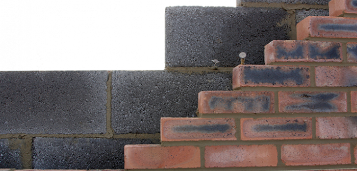
Bricks and wavelengths
Clutter data refers to obstacles above the ground such as trees and buildings. Cloud-RF has 9 classes of clutter data within the service which you can use and build with. Each class (Bricks +) has a different attenuation rate measured in decibels per metre (dB/m). This rate is a nominal value based upon the material density and derived from the ITU-R P.833-7 standard and empirical testing with broadcast signals in European homes.
A signal can only endure a limited amount of attenuation before it is lost into the noise floor. In free space attenuation is minimal but with obstacles it can be substantial. This is why a Wi-Fi router in a window can be hard to use within another room in the house but the same router is detectable from a hill a mile away.
The attenuation rate is an average based upon a hollow building with solid walls.
Common building materials attenuate signals to different amounts based on their density and the signals wavelength.
A higher wavelength signal such as L band (1-2GHz) will be attenuated more than VHF (30-300MHz) for example.
A long wavelength signal like HF will suffer minimal attenuation making it better suited to communicating through multiple brick walls.
The layer cake house
A brick house is not just brick. It’s bricks, concrete blocks, glass, insulation, stud walls, furniture and surfaces of varying absorption and reflection characteristics. Modelling every building material and multi-path precisely, is possible, given enough data and time due to the exponential complexity of multi-path but wholly impractical.
A trade-off for accurate urban modelling is to assign a local attenuation value. It’s local since building regulations vary by country and era so a 1930s brick house in the UK has different characteristics to a 1960s timber house in Germany. Taking the brick house we can identify the nominal value by adding up the materials and dividing it by the size.
For example, 2 x solid 10dB brick walls plus a 5 dB margin for interior walls and furniture would be 25dB. Divide this by a 10m size and you have 2.5dB/m. Using some local empirical testing you can quickly refine this for useful value for an entire city (assuming consistent architecture) but in reality the *precise* value will vary by each property, even on a street of the same design, due to interior layouts and furniture.
Range setup
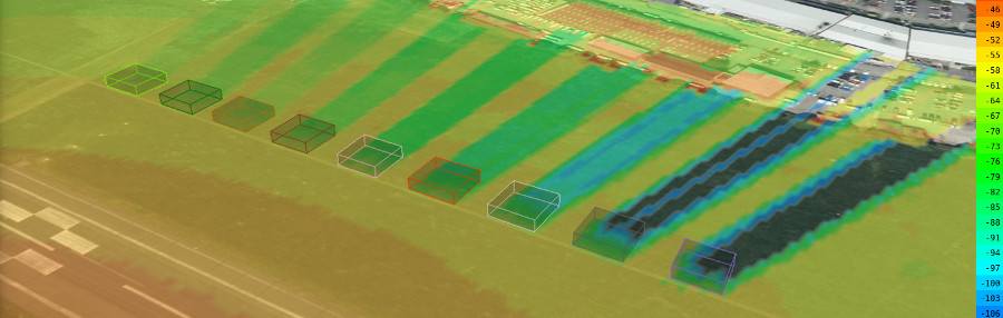
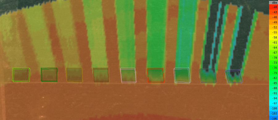
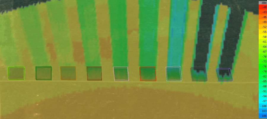
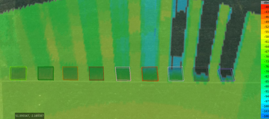
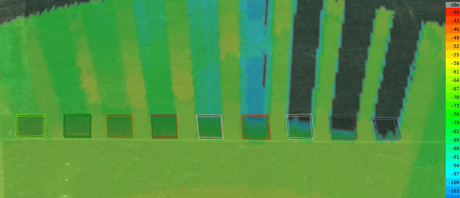
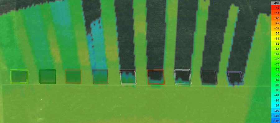
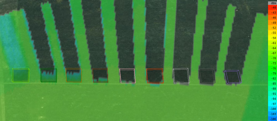
We created nine 4 metre tall targets using each of the 9 clutter classes in attenuation order from left-to-right, measuring 10x10m and fired radio-bulletsTM at them from a distance of 300m using the same RF power of 1W.
The following bands were compared: HF 20MHz, VHF 70MHz, UHF 700MHz, UHF 1200MHz, UHF 2.4GHz. SHF 5.8GHz.
The ITU-R P.525 model was used to provide a consistent reference.
Only the stronger direct-ray is modelled. Multipath effects mean that reflections will reach into some of the displayed null zones, with an inherent reflection loss for each bounce, but these are nearly impossible to model accurately and in a practical time.
Here are the results.
HF 20MHz
VHF 70MHz
UHF 700MHz
UHF 1200MHz
UHF 2.4GHz
SHF 5.8GHz
Findings
- Dense materials, especially concrete, attenuates higher frequency signals more than natural materials like trees
- Lower UHF signals perform much better than SHF with the same power
- Higher frequencies with low power can be blocked by a single house, even after only 300m
- HF eats bricks for breakfast!
Summary
Modern tactical UHF radios, and their software eco-systems, are unrecognisable from their cold-war VHF ‘voice only’ ancestors in terms of capabilities but have an Achilles heel in the form of material penetration. To get the best coverage the network density must be flexed to match the neighbourhood.
This is obvious when comparing rolling terrain with a urban environment but the building materials and street sizes in the urban environment will make a significant difference too. Ground units which communicated effectively in a city in one country may find the same tactics and working ranges ineffective in another city with the same radios and settings. Understanding the impact of material penetration will help planning and communication.
