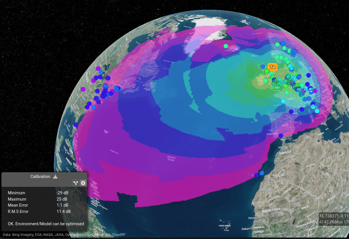
HF Ionospheric propagation, known as Skywave, has been added to the CloudRF API.
While Satcom offers clear advantages in terms of speed, bandwidth, and the ability to provide real-time, high-quality data transmission, HF remains a crucial alternative where cost, independence from satellites, portability, power efficiency, and resiliency are important.
Wide area simulation
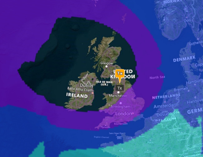
The new /hf/area API endpoint uses the proven VOACAP engine to simulate coverage for a given transmitter at a given time of day. It combines CloudRF’s familiar JSON interface structure (transmitter, antenna, receiver, environment) with VOACAP antenna patterns and temporal parameters (Month and hour).
The maximum range for the simulation is 10,000km which takes several seconds and like other (area) layers it can be exported to KMZ, GeoTIFF and SHP.
API reference: https://cloudrf.com/documentation/developer/#/Create/hf%2Farea
Link frequency prediction
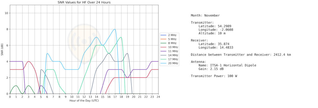
The new /hf/prediction API endpoint provides a HF frequency prediction capability, powered by VOACAP, for a given link. It uses the same workflow as the path tool whereby the transmitter is placed upon the map, the path tool is selected and the receiver is placed.
The output is a chart of frequency SNR values for the link across the HF band from 2 to 20MHz and hours of the day. As ionospheric activity varies considerably between day and night, the chart helps select an optimal frequency and can be exported to PNG.
API reference: https://cloudrf.com/documentation/developer/#/Create/hf%2Fprediction
HF parameters: Time and Sunspots
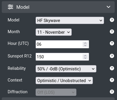
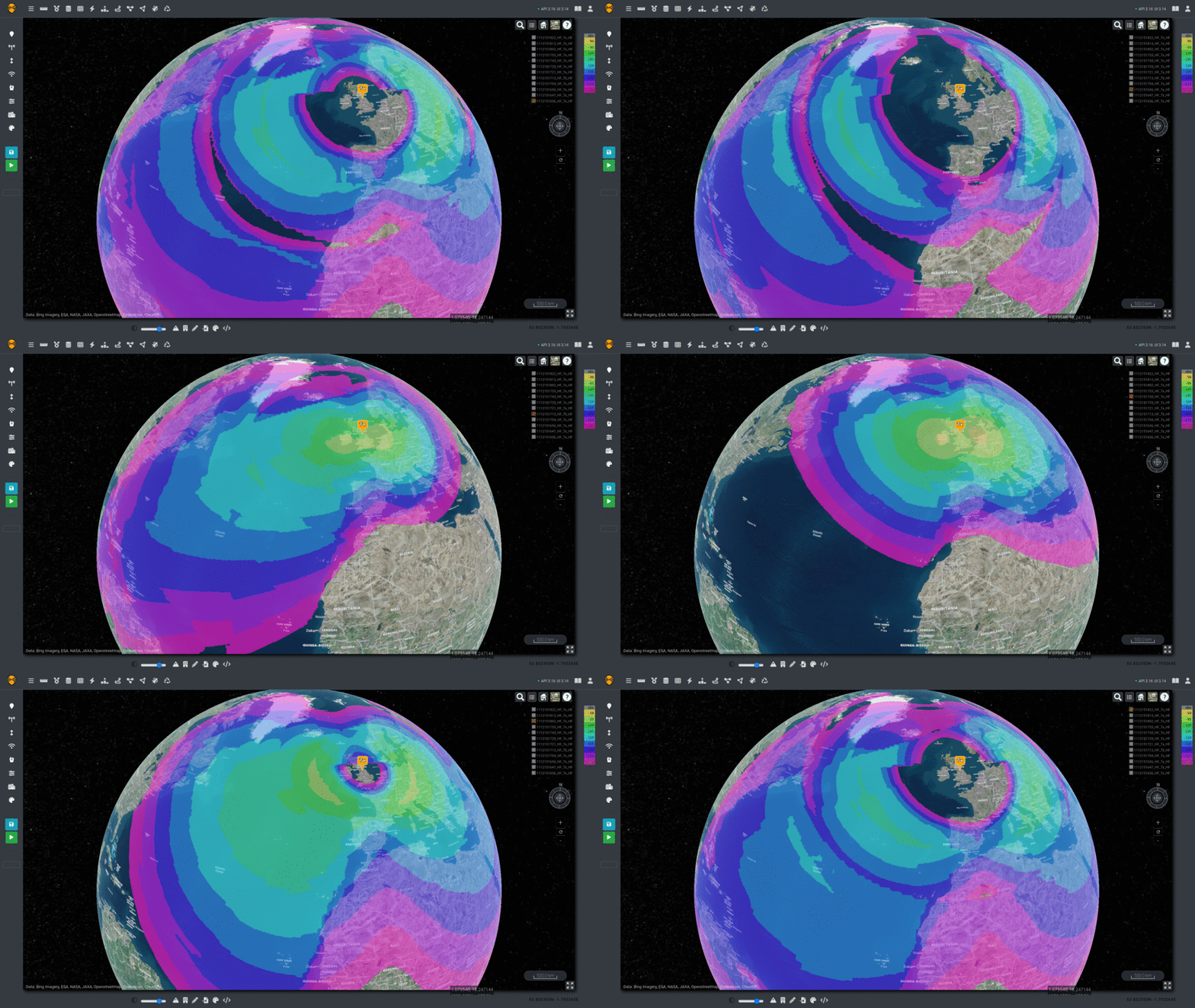
Time is critical with ionospheric communications so the “model” section has been extended to include three new variables.
Diffraction is disabled and the two familiar reliability and context variables can be tuned as with other models to match empirical measurements.
Month
The month is defined as a integer from 1 to 12.
The relevance to HF is that during the summer, solar activity, and therefore refraction, is increased.
Hour
The hour is defined as an integer from 0 to 23 and is in UTC.
The relevance to HF is that during darkness, the lower “D” layer collapses so RF which was previously attenuated is free to reach the higher “E” and “F” layers which increases both noise and global reach.
Sunspot R12 number
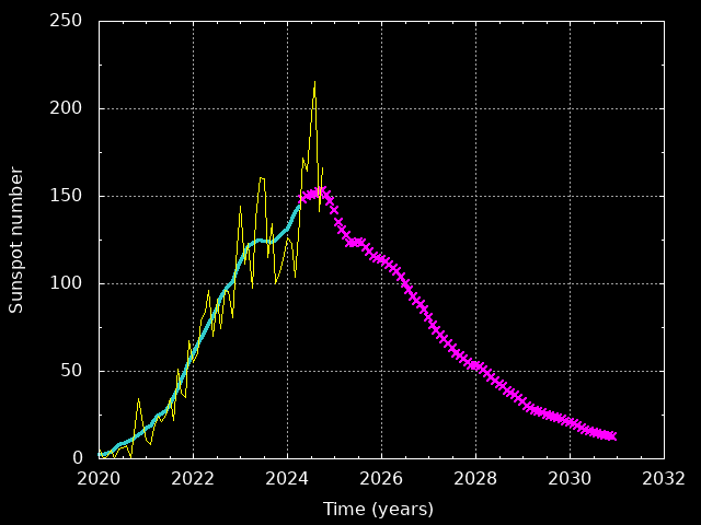
Solar activity follows a ten year cycle which can be predicted. The year 2024 is at the peak of this cycle so the “R12” number is high at ~150. In 2030 this will be low at (~25) and equivalent HF links will be more difficult.
Solar activity is subject to random bursts of radiation (Sporadic E) which makes predicting and calibrating HF communications harder than short range terrestrial links. Using empirical live measurements from sounders and crowd sourced networks, the random element can be mitigated but not removed.
HF Antennas
HF antenna theory is a complex art form. For example, the same physical antenna will produce very different propagation depending upon its height above the ground where reflection takes place.
The reflection depth varies by terrain so a swamp has a ground level water table but a desert could have a reflection height much deeper so an antenna may not need elevating much at all to achieve a link.
This reflection height determines the “take off angle”, and skip zone, whereby a tall antenna between two tall masts has a lower take off angle, and longer range compared with a waist height antenna which has a steep angle and relatively short range for Near Vertical Incidence Skywave (NVIS), which we have a separate model for.
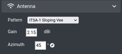
When selecting the HF model, you will be given a fixed list of VOACAP antenna patterns with which you can manipulate the gain, height and the azimuth. A typical gain figure for a dipole will be between 1 and 2.15dBi whereas a LPA could be 9dBi depending on elements.
| Antenna | Description | API code |
| ITSA-1 Horizontal Dipole | Center fed symmetrical design with arms matched to half a wavelength. Deployed broadside to the target. | 2 |
| ITSA-1 Horizontal Yagi | Directional array which can be steered to a target. | 3 |
| ITSA-1 Vertical Log Periodic | Highly directional array with a focused beam pointed at a target. | 4 |
| ITSA-1 Sloping Vee | Simple directional antenna which only requires one mast. Arms are measured to 1/2 the wavelength and staked out towards the target. | 5 |
| ITSA-1 Inverted L | End-fed mixed polarisation antenna capable of local groundwave and distant Skywave. 1/4 wavelength up and 1/2 wavelength along. | 6 |
| ITS-78 Inverted L | End-fed mixed polarisation antenna capable of local groundwave and distant Skywave. 1/4 wavelength up and 1/2 wavelength along. | 8 |
| ITS-78 Sloping Long Wire | Simple end-fed wire orientated towards the target. | 9 |
| ITS-78 Arbitrary Tilted Dipole | Dipole tilted to achieve maximum gain. | 10 |
| ITS-78 Terminated Sloping Vee | Simple directional antenna which only requires one mast. Arms are staked out towards the target and terminated with a load. | 11 |
Example HF API request
This simulation request is for a 10MHz half wave dipole, 8m above the ground, radiating 30W of RF power.
The month is November and the time is 8am UTC.
The sunspot R12 number is ~150 for late 2024 based on the solar cycle.
{
    "site": "Tx",
    "network": "HF",
    "transmitter": {
        "lat": "46.3936",
        "lon": "6.8835",
        "alt": "8",
        "frq": "10",
        "txw": "30",
        "bwi": "0.012"
    },
    "receiver": {
        "alt": "1",
        "rxg": "1",
        "rxs": "-125"
    },
    "antenna": {
        "txg": "2",
        "txl": "0",
        "ant": "2",
        "azi": "45"
    },
    "model": {
        "pm": "13",
        "pe": "3",
        "rel": "50",
        "month": 11,
        "hour": 8,
        "sunspots_r12": 150
    },
    "output": {
        "units": "m",
        "col": "HF.dBm",
        "out": "2",
        "nf": "-112",
        "res": "20",
        "rad": "5000",
        "bounds": {
            "north": 89,
            "east": 62.25,
            "south": 1.42,
            "west": -48.49
        }
    }
}
HF Calibration
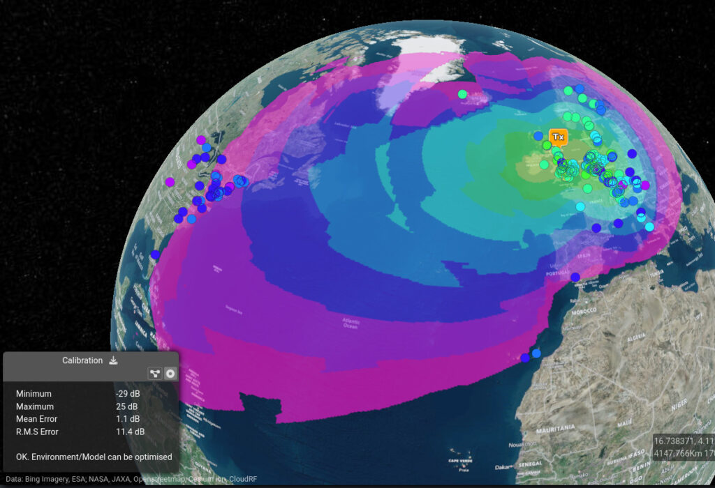
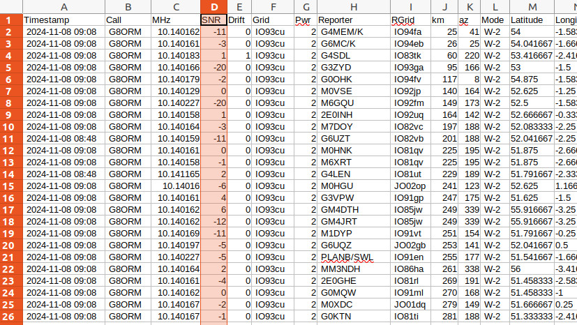
Using crowd sourced link measurements from the amateur Weak Signal Propagation Network (WSPR), the VOACAP engine can be calibrated using our native calibration utility. Data can be filtered by station and processed ready for import to the calibration utility. The data reports Signal-to-Noise (SNR) measurements which reference an unknown noise floor. We recommend an average value of -100dBm for the 10MHz noise as any error in measurement is less than the other variables such as the variable solar radiation and distant station antenna gain for example.
The WSPR data required pre-processing to convert the 6 figure Maidenhead grid squares to WGS-84 coordinates. The maidenhead python library is recommended for this.
Filtering a time window is critical due to the propagation changes which occur throughout the day. For example, you cannot calibrate measurements from day and night together but you can calibrate an hour as a separate file.
A look ahead
Now that we have published an API, we want to integrate it into some systems. ATAK is an obvious candidate for starters but a HF radio which can see into the future or a ALE modem which doesn’t need to radiate to know it can, or cannot, communicate.
This capability will be available with the next SOOTHSAYER release.
Credits
Credit to the many VOACAP developers and maintainers over the years who have maintained this powerful capability. It is arguably one of the most senior pieces of operational software in the commercial world.
We have only put a shell on this incredible engine but hope our API will introduce a new generation of software developers and communicators to the magic of HF.

