Recently, we added advanced diffraction models to CloudRF to complement our existing models. To validate the performance of the new Bullington and Deygout models, we took a field trip to the Highlands of Scotland to collect UHF measurements over rugged mountain terrain and through forests.
With these measurements we have validated and optimised our new models for this environment. We already had single-knife-edge diffraction, based on Huygen’s formula, and the Irregular Terrain Model (ITM) which uses Vogler diffraction. The Vogler model is known to be good but single knife edge has its limits which we have pushed.
Summary
The testing validated our investment into the complex multi-obstacle models we have added.
Both new models offer a significant improvement in accuracy, with no loss in performance for Bullington. We were able to model diffraction with higher accuracy over multiple challenging obstacles such as gradual convex slopes, ridges and valleys. Modifications have been made to the CPU and GPU engines which will be updated on CloudRF and SOOTHSAYER in due course.
Our key findings include:
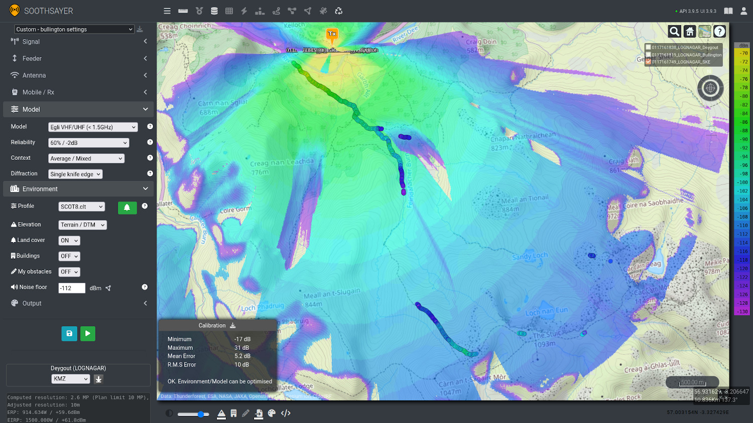
- Single-knife-edge was optimistic
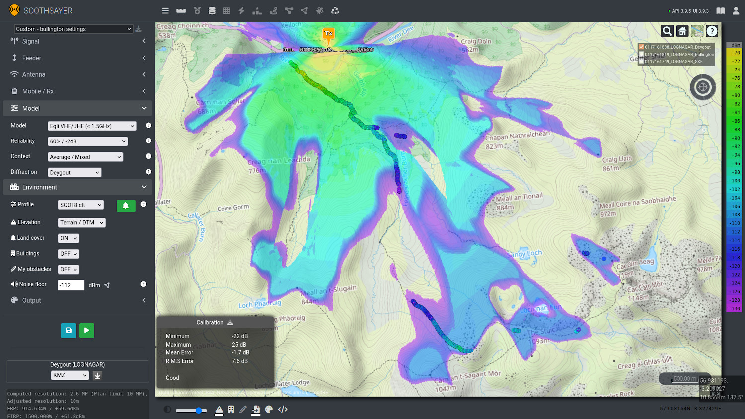
- Deygout was the most accurate, but slower
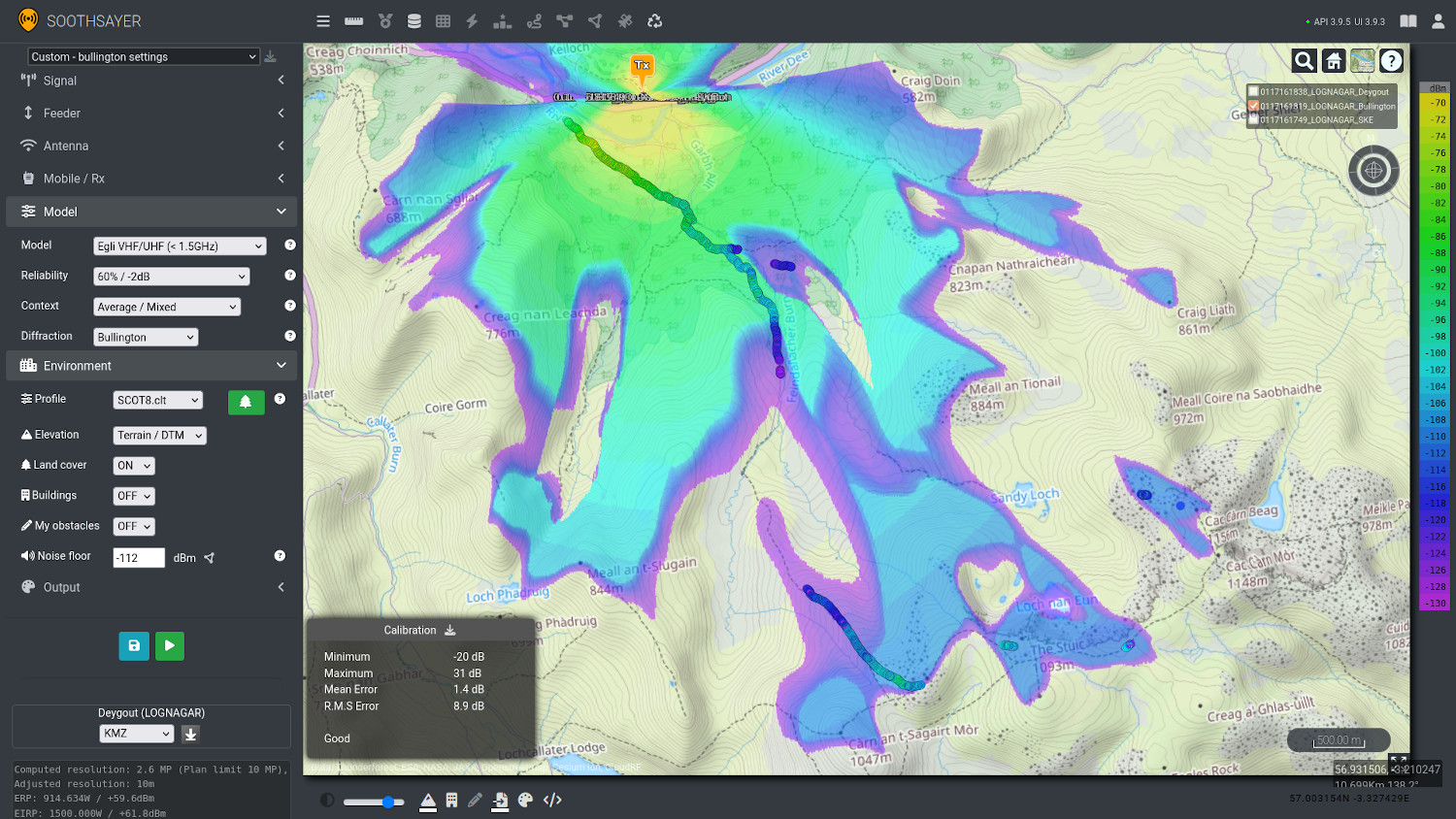
- Bullington provided the best overall performance
- 7.6dB accuracy achieved, including receiver error
- 2.4dB improvement on single knife edge model
Test environment
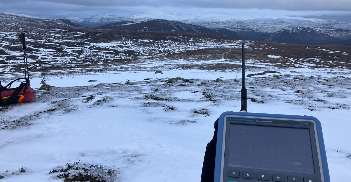
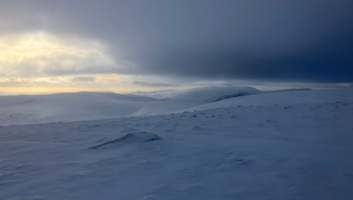
We selected a famously cold and remote valley in the Cairngorms national park for our test which has cell towers in the valley and a variety of local repeaters for TETRA, VHF and UHF PTT services. The challenging terrain is notoriously difficult for radio communications making it ideal for our purposes.
Using a test phone with 3dB of measurement error attached to the Vodafone 4G network and a portable Rohde and Schwarz spectrum analyser, we collected a variety of VHF and UHF measurements along a 22km circular mountain route covering a wide variety of terrain. From the data collected, the 800MHz LTE measurements proved the best examples of signal failure so we focused our post-analysis on these.
Throughout the LTE testing the phone attached to multiple local cells and experienced prolonged signal failure as expected in a remote mountain valley.
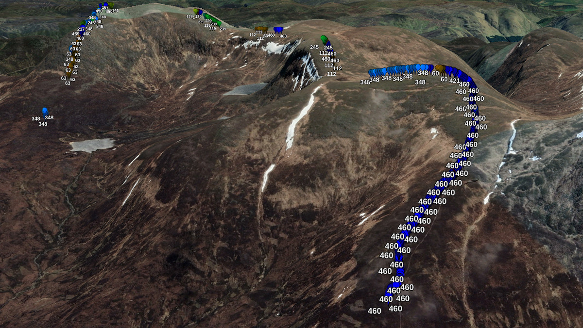
We filtered the results to isolate 634 RSRP readings from a single physical LTE cell, PCI 460, from which we would calibrate modelling. This cell was located at the start of our test route and was a high power LTE band 20 (800MHz) base station with 10MHz of bandwidth.
Trees and attenuation
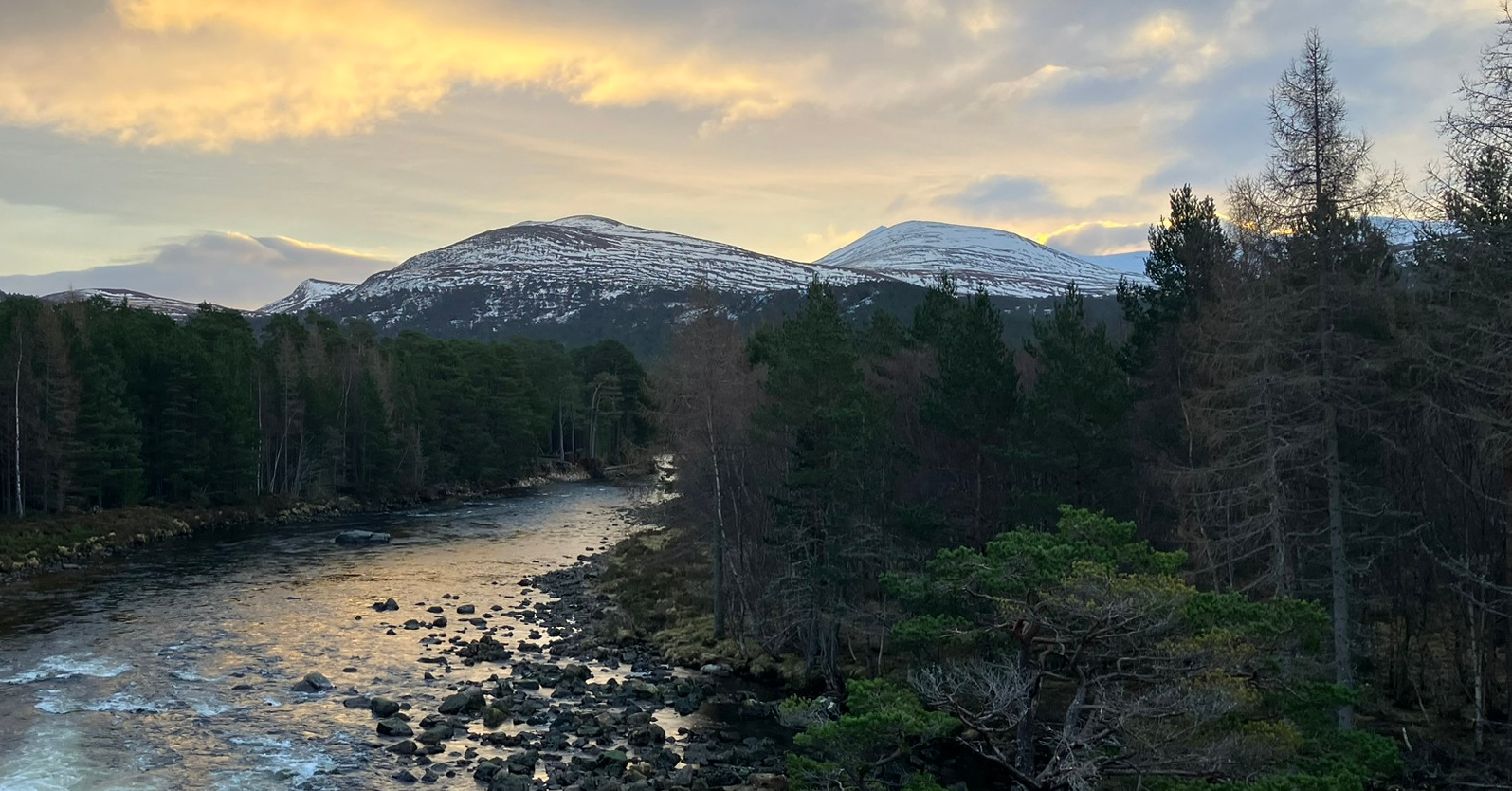
The first, and last, few miles of the circular route was a mature Scots pine forest. Unlike dense Scandinavian pine forests, this was sparse with a relatively high tree canopy. A lighter tree clutter profile was used to represent the attenuation from these trees which impact UHF propagation.
Convex hill and a loss of signal
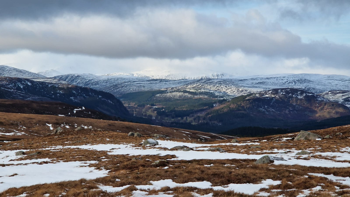
Beyond the forest, the route gained altitude into a mountain plateau where line of sight was lost. The shape of the hill meant any diffraction formula would have to model a gradual convex shape versus a simpler knife-edge obstacle.
The ascent and re-acquisition
As the route ascended a spur leading toward the ridge, the signal was reacquired beyond the snowline. This signal gain was gradual, starting as a diffracted signal from the lower convex hill which eventually became a direct signal at the summit, 7km away from the cell.
Summit switcheroo
The route traversed a high ridge which featured many gaps in our cell coverage in the test data. These gaps were because the LTE modem performed a handover to stronger cells which appeared as soon as they were “visible”. Depending upon the position along the ridge, it occasionally reverted to the original “460” cell at over 7km.
Descent into darkness
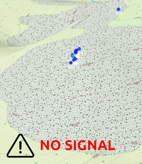
The steep descent from the ridge entered a obscured valley not visible from the cell.
This resulted in a prolonged loss of signal for several miles until the signal was reacquired toward the trees at the foot of the valley.
Results analysis
The LTE survey data was prepared as CSV and loaded into the CloudRF web interface for use with the coverage analysis tool. This provided live feedback on accuracy with user generated heatmap layers so the correct settings could be identified first visually using a fine colour schema and then numerically by the reported average error in decibels.
Whilst the site location and frequency was known, the power output was not so the first task was to match line of sight positions, such as on the ridge-line, to establish the power without any obstacles. From there, a tree clutter profile was created to match the tree measurements and finally the best model and context were selected. For this task, the generic Egli VHF/UHF model was chosen as a basic model on which to base the diffraction comparison.
As settings matured, the reported Root Mean Square (RMS) error reduced accordingly until it was below 8dB (including 3dB of receiver error). This was slightly better than the 8dB we achieved on our last field test with LTE800 previously and given the extreme context, spanning a diverse mountain range, this was an excellent improvement.
Subtracting receiver error gives modelling error in the range of 4.6 to 7dB; an excellent result for difficult terrain.
| Diffraction model | Mean error dB | RMSE error dB | Modelling error dB | Comment |
|---|---|---|---|---|
| Single knife edge | 5.2 | 10 | 7 | Optimistic. May show false positive coverage. |
| Deygout | -1.7 | 7.6 | 4.6 | Good. Can be conservative and is 50% slower but gives high assurance. |
| Bullington | 1.4 | 8.9 | 5.9 | Good. Can be optimistic but is as fast as KED and relatively accurate. |
Coverage results
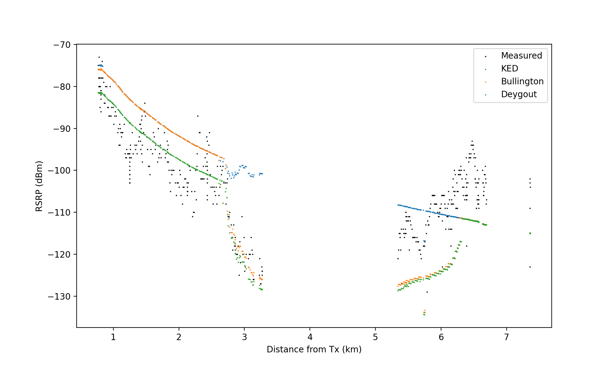
The scatter plot for the ascent to the ridgeline shows measured and simulated values. The steep drop at 2.5km and gap in results after 3.3km matches closely for the critical beyond line of sight region. The results start again once we ascended toward the ridge where the new models were conservative by 10dB whilst the simple knife edge model tracked the path loss curve – which was to be expected. All models aligned once line of sight was achieved at 6.3km.
Recommendations
The outcome of this testing has improved the accuracy of our diffraction models, identified optimisations for our clutter profiles and proved a simple path loss model can be very accurate beyond line of sight with the right diffraction model.
The API settings we used for the LTE800 cell and RSRP output are here. Note the custom clutter profile and fine colour schema.

{
    "version": "CloudRF-API-v3.9.5",
    "reference": "https://cloudrf.com/documentation/developer/swagger-ui/",
    "template": {
        "name": "Lochnagar LTE800",
        "service": "CloudRF https://api.cloudrf.com",
        "created_at": "2024-01-16T13:15:02+00:00",
        "owner": 1,
        "bom_value": 0
    },
    "site": "Site",
    "network": "LOGNAGAR",
    "engine": 2,
    "coordinates": 1,
    "transmitter": {
        "lat": 57.003155,
        "lon": -3.327424,
        "alt": 15,
        "frq": 806,
        "txw": 15,
        "bwi": 10,
        "powerUnit": "W"
    },
    "receiver": {
        "lat": 0,
        "lon": 0,
        "alt": 2,
        "rxg": 0,
        "rxs": -129
    },
    "antenna": {
        "mode": "custom",
        "txg": 19,
        "txl": 0,
        "ant": 0,
        "azi": 180,
        "tlt": 0,
        "hbw": 120,
        "vbw": 20,
        "fbr": 19,
        "pol": "v"
    },
    "model": {
        "pm": 11,
        "pe": 2,
        "ked": 2,
        "rel": 60
    },
    "environment": {
        "obstacles": 0,
        "buildings": 0,
        "landcover": 1,
        "clt": "SCOT4.clt"
    },
    "output": {
        "units": "m",
        "col": "PLASMA130.dBm",
        "out": 6,
        "ber": 0,
        "mod": 0,
        "nf": -120,
        "res": 10,
        "rad": 8
    }
}
Disclaimer
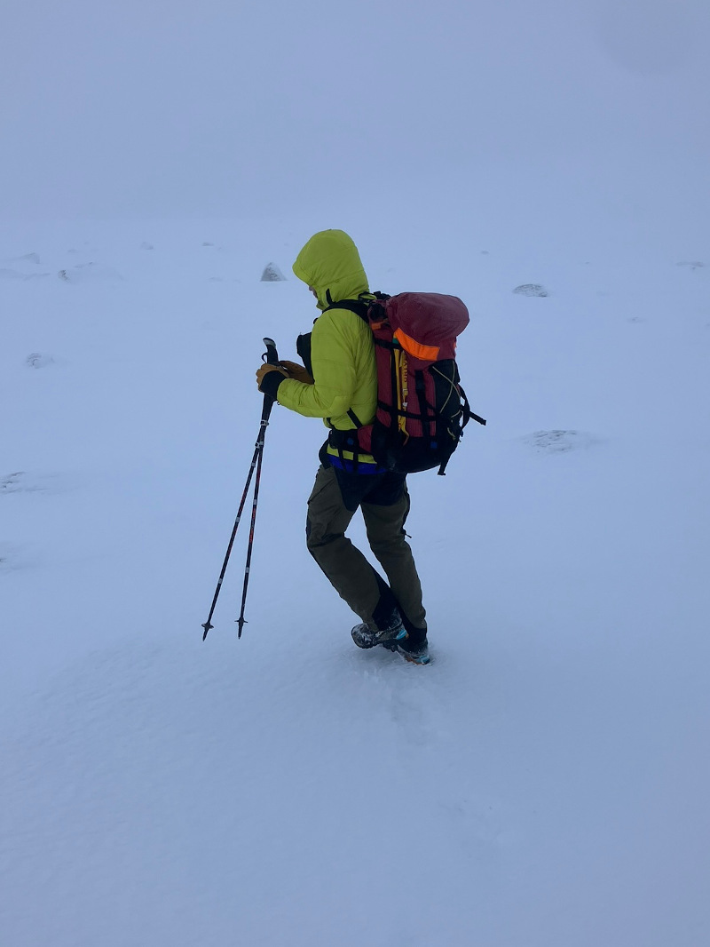
Climbing mountains in winter to test radio networks is dangerous, hard work which requires fitness, experience, skill and dedication to RF engineering. Only do this if you are serious about improving accuracy!
