True 3D multi-path
Following two years of R&D, our new 3D engine and API is live.
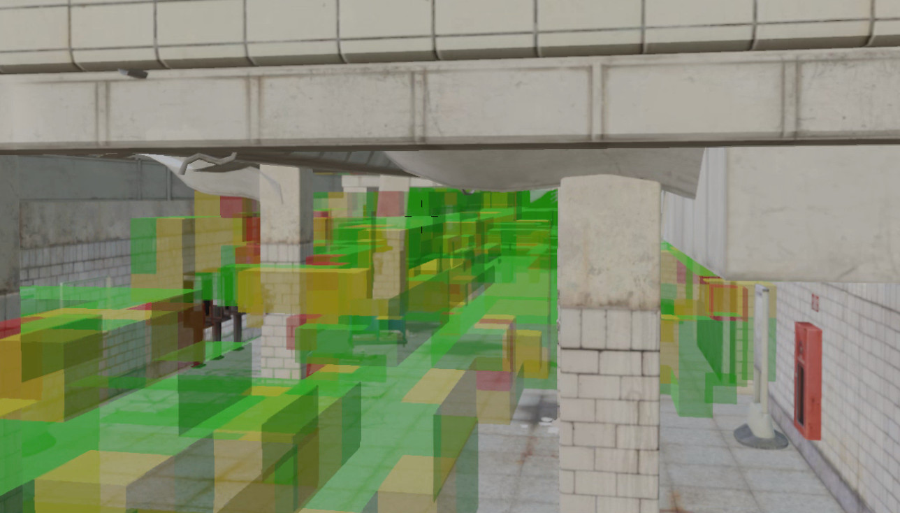
It uses an advanced volumetric design to simulate propagation in all directions making it more advanced than 2D engines which can only produce flat images. By design, it supports multi-path and phase tracking to model “fast fading” when signals collide making it well suited to challenging urban and subterranean environments.
Key features include:
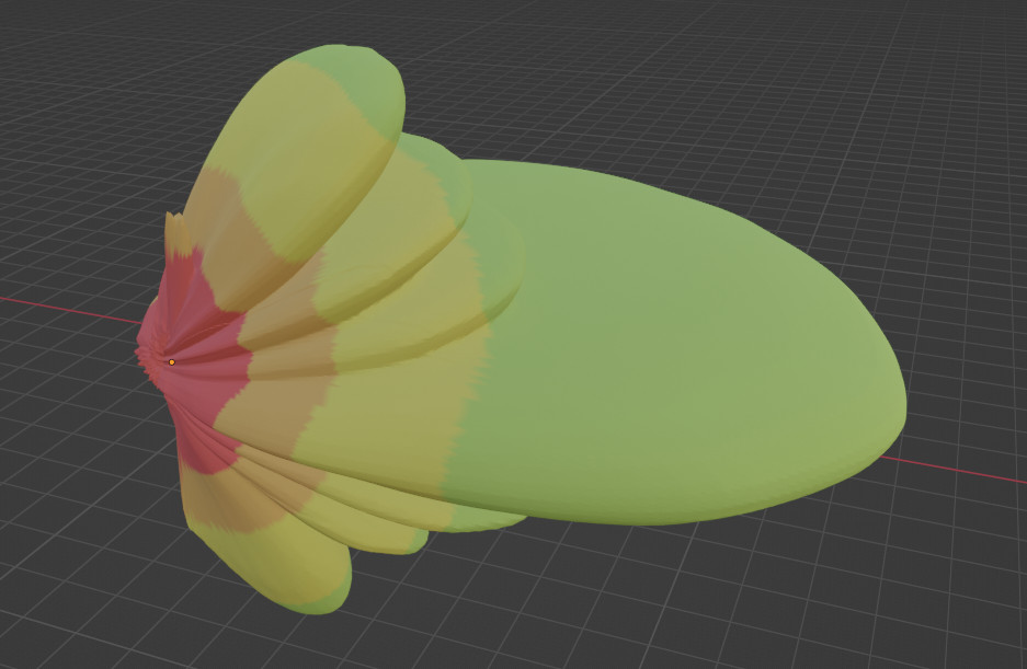
- 3D antenna patterns
- Configurable reflections (up to 10)
- Configurable material attenuation (dB/m)
- Configurable material reflectivity (dB)
- Configurable material diffusivity (Metal v Stone)
- Multi-site support (n transmitters)
- Phase tracking for multi-path effects (Constructive and destructive multipath)
- Configurable resolution from 10cm, subject to model size
CloudRF Blender plugin
An open file standard and an Open API
We’ve chosen the growing glTF 3D standard by the Khronos Group for our input and output. It is supported by most devices, GIS software, graphics engines and 3D viewers.
You can transform LiDAR point cloud scans into a glTF mesh using a number of free packages to exploit popular formats like LAS and LAZ.

As per our open architecture and API-first design, the 3D API is available now as an open API. You will require a premium CloudRF account and an API key to use it.
With the API, you can push up a model, perform coverage analysis, and view the output using a hosted viewer supported by popular browsers.
Multi-path visualisation
Everyone talks about multi-path, the behaviour of colliding radio waves but can they visualise it? Signals schools teach students that a “little movement” will cure a dead spot. That’s good but when a little more movement puts them back in a dead spot again it doesn’t solve the real issue, current software cannot practically do multi-path.
There are expensive ray tracing solutions designed for design engineers but not operators deploying equipment, or students even who are taught to move, but don’t know where to!
In the screenshot below, a directional 5G antenna is pointed towards Tower bridge in London. Where there is line of sight on the river Thames the signal is a solid green. Where there are reflections, the signal is patchy and adjacent to the bridge there is a notable area of destructive multipath in the middle of the river. This huge dead spot is caused by strong reflections coming from the south tower of Tower Bridge. The north tower isn’t as affected due to the angle of incidence which creates a longer reflection path, and weaker reflection.
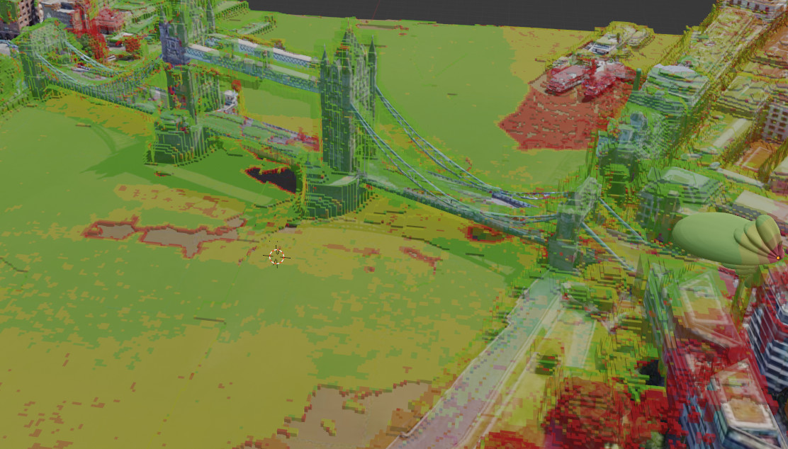
Destructive multipath in the middle of a river.
Viewer agnostic
As an open standards API our mesh output can be consumed by browsers, third party apps and AR viewers. We’ve already integrated it into a Hologram and the popular Blender 3D software and will add it to our web interface soon since we use Cesium which has supported glTF since 2014.
You can add glTF models direct into ESRI’s ArcGIS Maps SDK. Demo code is right here!
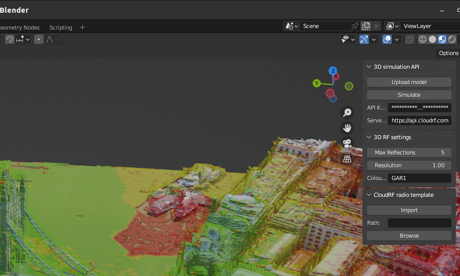
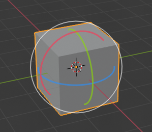
Blender plugin
Whilst developing this we used the popular Blender open source 3D platform to create obstacles and inspect output. We developed a plugin for Blender which we have open sourced so you can drive it directly from Blender. The plugin will upload your model and allow you to use it, along with CloudRF radio templates, to simulate RF coverage.
For more information on the plugin see here.
3D properties
Coordinates
Instead of a geographic projection like WGS-84, this engine uses XYZ coordinates relative to the model origin (x=0,y=0,z=0). This is better for modelling buildings in isolation like architecture designs which don’t exist!
When a building is placed upon the earth, the translation to these values should be performed by the client, such as Blender so ideally the user does not need to know what/where they are – it just looks right.
Up and Forward
Cartesian vector coordinates are more complex to express than latitude and longitude.
This is best left to the client like Blender for example. As a minimum the position is required as XYZ and for advanced usage the API allows “up” or “forward” XYZ directions to be used to express rotation. Different platforms do different things with coordinates so we have opened up our API to support as many as possible.
Materials
We’ve supported configurable clutter for years but with multi-path support we have extended support for both attenuation, reflection and diffusion. The glTF standard supports materials by standard with human readable names eg. “Wood”. You should match the materials you are using with the “Keys” section to capture variants in your model for example: “Wood”, “Oak Wood”, “Timber”.
Reflection loss
Measured in decibels, this is loss incurred by a reflection from a surface. Solid surfaces like Metal reflect most of the energy so have a low loss value of between 1 and 3 dB and softer surfaces like timber absorb more energy so have higher loss values of 3 to 6 dB.
Transmission loss
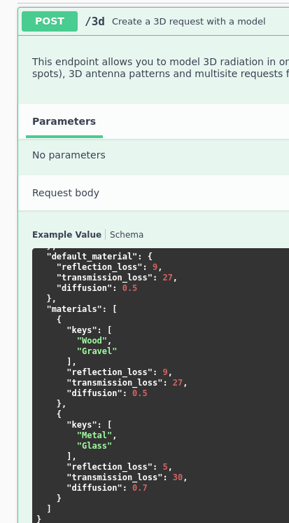
Measured in decibels per meter, this is absorption loss. These figures will be much higher than what you might have used with our other APIs since those are nominal values based on average attenuation through a house whereas these are the actual value for the material(s) (eg. brick) not the parent obstacle (a brick house).
For example; a brick house measuring 10m wide might have 2 blocking walls at 10dB each for a given UHF frequency.
With the 2D API, this would be represented as a attenuation figure of 20dB / 10m = 2dB. In the 3D API the brick wall would be the simpler 10dB!
The advantage of this is we can now model inside rooms with different materials and furniture – if you have the model…
Diffusion
Radio waves scatter when they hit a wall. The behaviour varies by the material so you can define this behaviour with the diffusion parameter. It’s a randomisation ratio from 0 to 10. At 0 there is no diffusion and you are only considering the input ray. With 0.1 a small amount of randomisation is occurring so the reflection is very predictable like a game of pool.
With 10.0 the reflections are truly random in all directions. This would be suitable for a gravel path for example.
Performance
Modelling a cube is harder than a 2D plane so this takes longer. How long depends upon your model size and resolution and reflections. Increasing reflections doesn’t add as much work as you might expect due to our efficient design but asking for 20cm resolution for an entire neighbourhood will leave you waiting for a few minutes.
Performance tips
- Start with 1m resolution and a small model
- Keep you input model minimal. If you have every pot plant in the town it will be a big mesh file and will take longer!
- Pretty photo realistic 3D tiles are pretty but take a long time to model. Go ugly early with basic models for speed.
Documentation
The swagger documentation is located here.
The blender plugin is located here.
