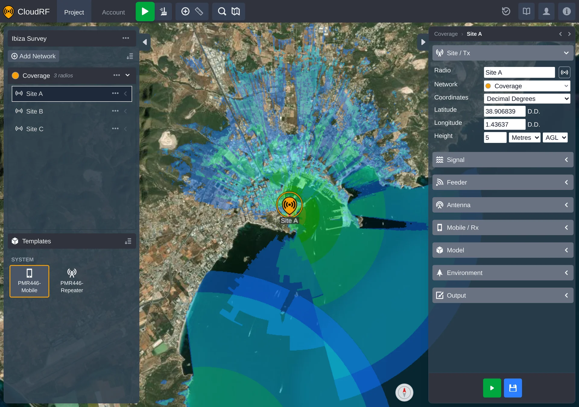
A radio is a single transmitter site: a position on the globe plus the full set of RF settings
that describe its equipment and how its signal is modelled. It's the object you'll work with most.
Select one to show its settings on the right sidebar.
The panel is divided into eight collapsible groups, listed below in the order they appear. Only
Site / Tx is open when you first select a radio.
Format used to enter the position: Decimal Degrees, Degrees Minutes Seconds, or MGRS / UTM.
Latitude / Longitude
Site position, in the chosen format. In MGRS / UTM mode the decimal fields become read-only and an MGRS field is added below them.
Height
Antenna height, with a Metres/Feet selector and an AGL/ASL selector beside it. AGL measures from the ground level at the site; ASL measures from sea level.
Saving a radio's icon and settings together as a reusable template is covered on the
Templates page.
The feeder cable, chosen from a list of standard coax types (Belden, LMR, RG-series and more), each with its own loss profile.
Coaxial length
Slider for the length of the feeder run between transmitter and antenna, in the project's distance unit.
Connectors
Number of connectors in the run, each adding a fixed loss.
Calculate Loss
When on, Loss is computed from the three fields above and the Loss box is read-only. When off, those three fields are disabled and you enter Loss by hand.
Loss
Total feeder loss.
ERP
Effective radiated power, in watts and dBm, from RF Power minus feeder loss plus antenna gain. Read-only.
EIRP
The same figure referenced to an isotropic radiator rather than a dipole. Read-only.
Efficiency
ERP as a percentage of transmit power, badged Good, Average or Poor. Read-only.
ERP, EIRP and Efficiency recompute as you change RF Power, feeder loss or antenna gain.
Height of the receiving antenna, with the same Metres/Feet and AGL/ASL selectors as Site / Tx.
Receive Gain
Gain of the receiving antenna.
Sensitivity
Slider and value for the threshold at which the link stops being usable - this is what sets the edge of coverage. Its unit and scale follow the Output group's Measured units, and the value is rescaled when you change that.
Apply a saved model preset. While a preset is selected the fields below show its values and are locked; choose Custom to edit them.
Model
The propagation engine, grouped into deterministic, cellular, empirical and special-purpose models.
RCS
Radar cross section of the target. RADAR model only.
Reliability
Statistical confidence applied to the model, from 50% / -0dB (optimistic) to 99% / -9.8dB (conservative).
Context
How forgiving the model is about the surroundings: Conservative / Urban, Average / Mixed or Optimistic / Unobstructed. For HF NVIS this becomes the D, E or F ionospheric layer instead.
Diffraction
Method used to account for terrain obstruction: Off (LOS), Single knife edge, Bullington, Giovanelli, Deygout 94 or Epstein-Peterson.
Apply a saved environment preset, as with Model above.
Profile
Clutter profile used for land cover loss, from the profiles on your account.
Elevation
Surface / DSM models the terrain with everything standing on it; Terrain / DTM models bare earth.
Land cover
Whether the clutter profile is applied at all.
Buildings
Whether vector building data is included as an obstruction.
My obstacles
Whether your own custom clutter is included.
Noise floor
Receiver noise floor in dBm. The database button beside it switches to the noise database for the site instead of a fixed value, which is what the map's RF Noise Floor overlay needs.
What the heatmap measures: Path Loss (dB), Received Power (dBm), Field Strength (dBµV), Signal to Noise Ratio (dB), RSRP (dBm) or Throughput (Mbps / kbps). Changing it also switches to that unit's default colour schema and rescales the Mobile / Rx sensitivity.
Colour schema
Palette used to render the heatmap, filtered to those valid for the measured unit.
Engine
Whether the calculation runs on GPU or CPU.
Resolution
Ground resolution of each heatmap pixel, from 1m / 3ft to 300m / 984ft.
Radius
Maximum calculation radius from the site, in km or mi.
Megapixels
Read-only estimate of the output size from radius and resolution.
When a network has mesh or merged heatmaps enabled, its Mobile / Rx, Model, Environment and Output
groups are set at network level instead. Those four groups on the radio show an Applies to all
radios in network banner, and editing them there edits the network's shared settings. See
Networks.
Each radio can be calculated on its own, rather than recalculating the whole network: select the
radio and press the green button at the bottom of the right panel, or press
Space - see hotkeys.
The button beside it saves the radio as a
template.